PN25080
Start-Up & Operation 5 - 5
TRIO-WIRL INSTRUCTION MANUAL
5.2.4 Contact Output Connections
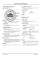
The value of the resistance R
E
is a function of the sup-
ply power U
B
and the selected signal current I
B
(refer
).
R
E
=
5.3 Converter Configuration
5.3.1 Data-Entry Check
The measurement system has been configured by the
factory prior to shipment based on the information
included with the customer order. All the required val-
ues have been entered. Because the instruments can
be installed to measure liquids or gases, it is recom-
mended that the following software parameter settings
be checked at start-up:
4.Which flowrate units are to be used for the display
indications and for the totalizer values?
5.Enter the desired flow range in the units selected
above in the parameter
Qmax Operating Mode
.
Entry range: 0.15 to 1.15 x Range
max
actual.
6.Check the low flow cutoff value in the parameter
Qmin Actual
Entry range: 0 to 0.1 x Range
max
.
7.Select the units for the internal and external totalizers
in the parameter
Units Totalizer.
8.The response time of the converter can be set in the
parameter
Damping
.
Default setting is 3 sec.
9.Select submenu
Display
and select desired values,
e.g.:
For main display select percent
For multiplex display select totalizer values
The measurement system is now ready for operation.
5.3.2 Additional Configuration Information
5.3.2.1 Meter Size
This parameter is used to define the size of the
installed flowmeter since the same converter can be
used for all flowmeter sizes.
The meter size is set at the factory for the converter’s
assigned flowmeter primary (see Instrument Tag).
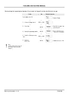
Parameter
Action
1. Meter size
Select Meter Size. The displayed value must
be identical to the size listed on the Instr. Tag
2. Operating mode
3. k-Factor
Select k-Factor. The displayed value must be
identical to the value listed on the Instr. Tag.
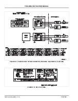
Con-
tact
Out-
TRIO-WIRL
Input, SPC etc.
with U
B
= 16-30 V
41
42
FIGURE 5-11 CONTACT OUTPUT CONNECTION
U
B
I
B
-------
U
B
in V
I
B
in mA
R
e
min
= 2 k
Ohm
R
e
m
ax
=
8
0
kO
hm
FIGURE 5-12 RELATIONSHIP R
E
AT THE
CONTACT OUTPUT AS A FUNCTION OF
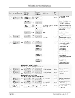
Mass Units
Volume Units
Parameter
Action
Parameter
Action
Operating
mode
Mass
select
Operating mode
Volume, Normal
Standard, Actual
select from
table
Density units
Qm
from table Units
Qv/Qn/Qs/
l/min
select from
table
Operating
density
enter
Normal factor (only
for Qs, Qn)
enter
value
Units Qm
kg/s
from table


