PN25080
Start-Up & Operation 5 - 7
TRIO-WIRL INSTRUCTION MANUAL
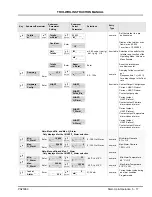
5.3.2.5 Submenu Pulse Output
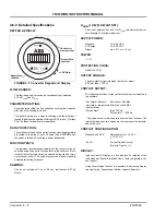
PULSE FACTOR
This menu is used to configure the scaled pulse output to the
user requirements.
Pulse Factor range is 0.001 - 100
The pulse factor is the number of pulses per selected flow unit.
PULSE WIDTH
If the pulse output function is to be assigned to the con-
tact output it is necessary that the parameter “I/HART/
Pulse_Bin“ be selected in the menu „Hardware Config“.
Otherwise this menu is hidden.
Pulse Width range is 1 - 256 ms
The pulse width (length of the pulses) for the scaled
pulse output can be set between 1 and 256 ms.
The program monitors the relationship of the pulse
width to the period of the maximum pulse frequency (at
115 % flowrate). If an on/off ratio
≥
50 % results, a
warning is displayed and the old value is retained.
SUBMENU ERROR REGISTER
This menu contains the error register and the supply
power interruption counter.
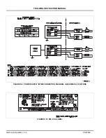
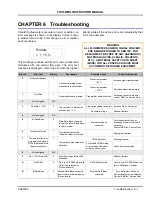
ERROR REGISTER
Displays the error register contents.
All errors detected are permanently stored in the error
register, whether they occurred momentarily or for a
long time period.
Every number in the error register display represents a
specific error type.
Display:
The error register can be cleared by pressing the
“ENTER“ key.
MAINS INTERRUPT
The Mains Interrupt display shows the number of times
power was turned off or interrupted to the converter.
The converter counts the number of times the supply
power was turned off or interrupted and displays the
total. The mains interrupt counter can be reset with the
command “Reset Error”. This parameter is located at
the Service level and requires entry of the Service
Code number for access.
5.3.2.6 Normal Factor (see Section
When Normal conditions are:
P = 1.013 bar (14.5 psi)
T = 0
o
C (32
o
F)
Since the mass flowrate at both conditions is equal the
following equation is also applicable:
Pulse
factor
Pulse
width
Error
Register
Error
. . . 3 . 5 6 . . .
Error No.
Error
Priority
0
1
2
3
4
5
6
7
8
9
A
B
Steam calculations
Front End
Not Assigned
Flowrate > 115 %
Not Assigned
M-Data Base
Totalizer defective
Temperature
Not Assigned
Qv > 115 % QmaxDN
Kit-FRAM
B-Data Base
7
0
N/A
2
N/A
0
1
7
N/A
2
9
0
Mains interrupt
Q
N
Q
V
--------
1.013
bar p
+
(
)
1.013
bar
---------------------------------------
273
273
T
+
(
)
-------------------------
×
=
Q
N
Q
V
--------
ρ
V
ρ
N
------
=
....... =
OK
.... 3.56... = Error codes


