PN25080
Start-Up & Operation 5 - 13
TRIO-WIRL INSTRUCTION MANUAL
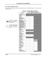
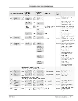
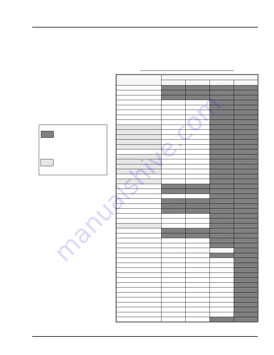
5.5.3 Top-Level Menu Structure
The table to the right lists all of the top-level menus contained in the TRIO-WIRL firmware vs. the four menu pro-
gramming modes:
TABLE 5-1. TOP-LEVEL MENU STRUCTURE
Menu Item
Menu Programming Levels/Modes
Locked
Standard
Specialist
Service
Program Level
Prog. Protection Code
Language
Primary
Meter Size
Median K-Factor
Schedule Correction
Flow Mode
Unit Density
Reference Density
Normal Density
Compressibility
Standard Conditions
Unit Temperature
Reference Temperature
Unit Pressure
Pressure P
oper
ABS
Volume Extension
Unit Q
vol
Unit Q
m
QmaxDN Oper
Qmax
Qmin Operating
Totalizer
Damping
Hardware Config.
Iout at Alarm
Pulse Factor
Pulse Width
Display
Error Register
Self Check
Instr. Address
Instrument No.
Order No.
PT100 Sensor
Linearization
D-Base Handling
Init Flash
Flash Checksum
Adjust I=4mA
Adjust I=20mA
Min. Current
DSP Par
Vib Par
Temp Par
Service Display
TRIO-WIRL Firmware ID
Indicates the available
menus for the given pro-
gramming mode.
Indicates
Menu Items
that appear depending
on other menu selec-
tions.

