background image

Operation Manual / TPS48-D/E.. - TPS61-D/E..

2  Safety / 2.9  Periodic checking of the pressure vessel

© Copyright 2020 . All rights reserved.

HZTL2410_EN

Rev.F

March 2020

2.9 Periodic checking of the pressure vessel

The pressure vessels used by ABB, such as those for wet or dry cleaning,
are so-called "simple pressure vessels".

¡

The locally applicable legal regulations regarding periodic checks of
the pressure vessels must be observed.

¡

The operating company is responsible for the safe operation of the
pressure vessel.

 WARNING

Danger due to pressure vessels

The operating company must make sure the pressure vessels are in
proper working condition and monitor them. Necessary repair or main-
tenance work must be carried out without delay and the required safety
precautions must be taken.

u

Pressure equipment must not be operated if it has defects.
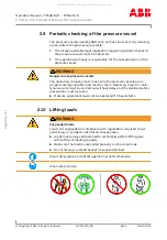
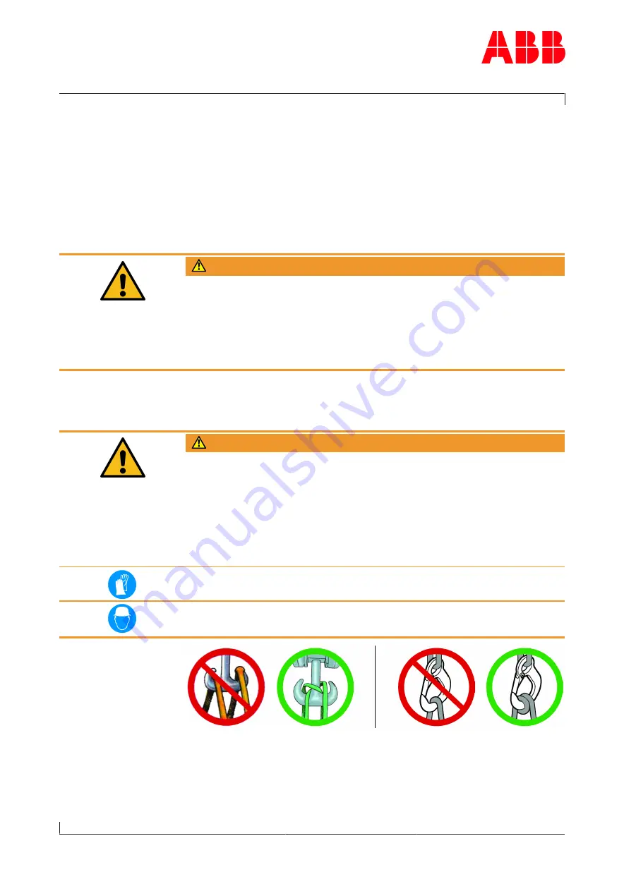
2.10 Lifting loads

 WARNING

Suspended loads

Loads not suspended in compliance with regulations may lead to per-
sonal injury or accidents with fatal consequences.
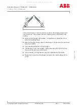
u

Loads must always be fastened to technically perfect lifting gear
with sufficient loading capacity.

u

Make sure the load is suspended properly on the crane hook.

u

Do not let anyone stand beneath a suspended load.

Wear safety gloves to protect against mechanical hazards.

Wear safety helmet.

Page 

26

 / 

111

All manuals and user guides at all-guides.com

Summary of Contents for TRS 61D01

Page 1: ...TPS 61D01 HT846638 nMmax 587 t Mmax 650 nBmax 558 t Bmax 620 1 s C 00650 8 50 50 Year 2021 Application according to the Operation Manual kg HZTL2410 English TPS 61D01 Original Operation Manual All ma...

Page 2: ...components depends on the load profile turbine inlet temperature suction air temperature and turbocharger speed In case the operation conditions differs significantly from what is considered to be no...

Page 3: ...fety instructions 15 2 5 Warning plates on the turbocharger 16 2 6 Safe operation and maintenance 17 2 7 Hazards during operation and maintenance 20 2 8 Deflagration on gas engines 25 2 9 Periodic che...

Page 4: ...8 1 Introduction 78 8 2 Module weights 81 8 3 Disassembling and assembling turbocharger 82 8 4 Axial clearance A and radial clearance B 95 8 5 Radial clearances N and R 96 8 6 Table of tightening torq...

Page 5: ...It provides important information in order that the turbocharger can be operated safely correctly and efficiently This Operation Manual complements and expands existing national reg ulations concerni...

Page 6: ...and function 1Suction branch filter silencer 8Gas outlet flange 2Compressor casing 9Nozzle ring 3Diffuser 10Turbine casing 4Bearing casing 11Turbine end bearing flange 5Axial thrust bearing 12Compres...

Page 7: ...e ambient air through the exhaust gas pipe which is connected to the gas outlet flange 8 The air which is necessary for operation of the diesel or gas engine and is compressed in the turbocharger is d...

Page 8: ...e equipment is used for any other purpose ABB Turbocharging reserves the right to reject all warranty claims State of the art This turbocharger was built according to state of the art technology and i...

Page 9: ...en handling VCIs VCI products are not hazardous in the sense of the Hazardous Sub stances Ordinance Nevertheless the following points are to be ob served when handling VCIs u Ensure good room ventilat...

Page 10: ...rbochar ger must be inspected by an ABB Turbocharging Service Station and repacked u Inspect the package for damage If the package is damaged the tur bocharger must be inspected by an ABB Turbochargin...

Page 11: ...e equipment NOTICE The manner in which personnel work on and with the turbocharger with regard to safety and risks is to be checked on a regular basis in accord ance with the Operation Manual u If the...

Page 12: ...bocharger must only be operated and serviced by trained and au thorised personnel Basic mechanical training is a prerequisite Design variants This document is valid for different design variants of tu...

Page 13: ...he product Definition of mandatory signs Mandatory signs show the protective equipment to be worn for a task The mandatory signs are described in chapter Safety and must be com plied with Definition o...

Page 14: ...2 Turbocharger operating limits during operation Recommended inspection and replacement intervals for turbocharger compon ents 03 Inspection interval for plain bearings in 1000 h 04 Replacement interv...

Page 15: ...ally apply only when running at overload 110 during trials on the engine test bed These limits can also be permitted during op eration for special applications Operation above nMmax and tMmax is not p...

Page 16: ...vance of the safety instruc tions are the consequence of unsatisfactory and improper execution of maintenance and inspection work The operating company is responsible for access to the turbocharger as...

Page 17: ...2 4 Definition of Safety instructions The following symbols and terms used in this manual concern safety or refer to possible hazards WARNING Definition of warning Serious personal injuries and even a...

Page 18: ...ed places or are not legible then proceed as follows u Order new warning plates from ABB Turbocharging Service Stations u Remove unreadable warning plates u Clean and degrease surfaces provided for wa...

Page 19: ...e under physical or mental stress u Work only with suitable tools as well as equipment and working ma terials that are in perfect condition u Electric tools must be solidly earthed and connecting cabl...

Page 20: ...ional perform ance to person responsible u If damage is discovered immediately shut down turbocharger and se cure it against inadvertent or unauthorized use u When switching on auxiliary power sources...

Page 21: ...terrupted especially with an external oil supply u Put the engine into operation only after all parts have been refitted properly CAUTION Mechanical work on the turbocharger Possible damage to or dest...

Page 22: ...ith instructions u During maintenance work secure the rotor against unintentional ro tation Mechanical hazards when working on the turbocharger During maintenance work various risks can occur through...

Page 23: ...protection Wear ear protection Hazards due to hot surfaces and substances During operation turbocharger surfaces and attached parts as well as operating materials lubricating oil become hot The surfa...

Page 24: ...s ory Wear safety gloves to protect against thermal hazards Hazards due to operating and auxiliary materials Operating and auxiliary materials are substances used for operation or the execution of mai...

Page 25: ...and water due to improper disposal can lead to environmental damage u Handle operating and auxiliary materials carefully u Heed the instructions for use safety data sheets and hazard notices on the c...

Page 26: ...re when removing old insulating materials u Dispose of insulating materials properly and in an environmentally compatible way in accordance with applicable local regulations Wear safety goggles Wear a...

Page 27: ...tand a deflagration with a transient pres sure increase of 12 bar ABB Turbocharging recommends that following a deflagration event the turbocharger undergoes an inspection of the following points Posi...

Page 28: ...ake sure the pressure vessels are in proper working condition and monitor them Necessary repair or main tenance work must be carried out without delay and the required safety precautions must be taken...

Page 29: ...harger assemblies components as described in re spective handling steps u Before attaching slings allow turbocharger components to cool down maximum 80 C u Use suitable protection at sharp edges u Com...

Page 30: ...rbine specifications and bearings used varying amounts of contaminants have to be filtered out of the lubricating oil to avoid dangerous wear of the bearing parts The standard oil filter specification...

Page 31: ...inlet temperatures are shown in the following chart 1 Kinematic viscosity mm2 s cSt 2 Oil inlet temperature C A Permissible range CAUTION Falling below the minimum oil inlet temperature Serious machi...

Page 32: ...for operation Oil pressure in front of turbocharger bar Normal operation 2 0 4 5 Engine start cold oil permissible for maximum 15 minutes 8 0 Engine idling 0 2 Pre and post lubrication engine stopped...

Page 33: ...outlet depends mainly on lubricating oil temperature and pressure at the oil inlet engine load and turbocharger speed exhaust gas temperature The maximum permissible oil temperature at the outlet is...

Page 34: ...of dirt and solid matter in the oil can cause serious damage to the machine or property u During initial commissioning and after all service work the complete lubricating system must be flushed thoro...

Page 35: ...and behind turbine u Measure air temperature in front of and behind compressor The measured values must be compared with the values in the accept ance test report while taking different operating con...

Page 36: ...after gas outlet u Inspect exhaust gas duct line in front of and after turbine for any combustion deposits foreign matter or residual water Clean and re move u Inspect air supply line or filter silenc...

Page 37: ...und pressure level of emissions1 reaches a maximum of 105 dB A near the filter silencer and over the entire speed range The following prerequisites must be fulfilled on the turbocharger in or der to o...

Page 38: ...hts reserved HZTL2410_EN Rev F March 2020 Suggestion for noise insulation of the bellows 01 Compressor casing 04 Insulation pads 02 Bellows 05 Insulation mat at least 15 mm 03 Charge air duct scavengi...

Page 39: ...carried out too late can lead to excessive contamination and wear as well as operating failures u Carry out service work at specified time intervals CAUTION Shortened service intervals Despite observa...

Page 40: ...e manufacturer s instructions Oil filter u Clean or replace oil filter in supply line to turbocharger when engine is not running 4 2 3 Service work in accordance with instructions on rating plate In g...

Page 41: ...easured values must be entered reg ularly in the engine manufacturer s engine logbook Engine performance and speed Air intake temperature Exhaust gas temperature in front of and behind the turbine Pre...

Page 42: ...hose non rotating components that are exposed to hot gases Decisive in this respect are various influencing parameters which can drastically shorten the replacement intervals of these parts in extreme...

Page 43: ...d preparation Load profile thermal load cycles also starts stops emergency shut downs Gas inlet temperature Frequency and execution of turbine and compressor cleaning Turbocharger specification System...

Page 44: ...ed CAUTION Do not use cables as a climbing aid If you pull the speed measurement cables too hard contacts can be pulled out u Do not tension the speed measurement cables 86505 A Speed sensor cable not...

Page 45: ...out u Reduce engine performance immediately until the highest turbochar ger speed no longer exceeds 70 of nBmax u If the engine cannot be stopped continue to run at this reduced en gine performance o...

Page 46: ...ety gloves when removing the cable connector and speed sensor Wear safety gloves to protect against thermal hazards u Reduce engine performance to the idling speed then stop the engine u Switch off th...

Page 47: ...in the chapter Troubleshooting 4 5 Stopping the engine CAUTION Stopping the engine of oil cooled turbocharger version Heat in the turbocharger must be dissipated by the further circulating lubricatin...

Page 48: ...ning is carried out too often this can lead to damage and corrosion on the components u If cleaning during operation is not sufficient to achieve acceptable values regarding thermal load and engine pe...

Page 49: ...nbalance Periodic cleaning of the compressor during operation prevents or delays any major increase in contamination But it never replaces the regular service work where the turbocharger is completely...

Page 50: ...ION Corrosion and deposits when cleaning Damage and impairment of turbocharger parts due to salt water and cooling water additives u Don t use salt water for cleaning but only clean fresh water CAUTIO...

Page 51: ...y mounted water vessel is suitable only for those applications where a negative pressure exists in front of the compressor wheel not used for blowers connected in front of the compressor or high press...

Page 52: ...the cleaning cycle until a stabilisation period of at least 10 minutes has elapsed NOTICE Whether or not cleaning has been successful can be seen from the char ging or flushing pressure and also from...

Page 53: ...performance After stopping the engine the rotor can become stuck in contamina tion deposits Experience with turbocharger operation shows that the intervals between overhauls can be extended if cleani...

Page 54: ...ntervals prove incompatible with engine operation please contact ABB Turbocharging Cleaning method Turbine components are cleaned during operation by using the wet cleaning method described below This...

Page 55: ...e of thermal shock in combination with a subsequent flushing phase Process with long water injection time 10 minutes cleaning The cleaning process with a long water injection time is used for tur boch...

Page 56: ...emperature at the turbine inlet can be up to 100 C higher than the exhaust gas tem perature after the cylinder This should be taken into consideration when setting the operating point before cleaning...

Page 57: ...racteristic com ponent Conditions short Water injection time long Water injection time Engine load guide value 20 40 Turbine inlet temperature TTE before water injection 350 400 C 350 430 C Water supp...

Page 58: ...ing engine load again This completes the turbine cleaning process Cleaning parameters during the process TPS Temperature in front of the tur bine during clean ing C Water volume flow 1 dm3 min Injecti...

Page 59: ...eaning parameters during the process TPS Temperature in front of the tur bine during cleaning C Water volume flow 1 dm3 min Injection time min Stabilising phase before after wa ter injection min 48 53...

Page 60: ...d turbine casings have protective coatings which can also be damaged u Only use soft tools such as cloths brushes or wire brushes u In the event of heavy contamination the cleaning methods that have b...

Page 61: ...81265 u Clean filter ring 81265 as required or every 500 operating hours and replace after the fifth cleaning operation at the latest The degree of contamination of the filter ring depends on the cle...

Page 62: ...damp cloth u Have absorption segments which are heavily contaminated replaced by an official ABB Turbocharging Service Station Fitting the filter silencer u Insert the absorption segments 81136 into t...

Page 63: ...ording to the material safety data sheet u Comply with local legislation Wear safety goggles Wear safety gloves to protect against chemical hazards Wear a respiratory mask to protect against gases The...

Page 64: ...Wear safety goggles Wear safety gloves to protect against chemical hazards Wear a respiratory mask to protect against gases Baked layers of contamination for example from heavy fuel oil or coked oil...

Page 65: ...the cartridge group immediately after cleaning Compressor wheels or turbines may be heavily contaminated due to heavy fuel oil operation or coked oil Such contamination may possibly no longer be remo...

Page 66: ...p this can im pair the function of the turbocharger and damage parts inside the cart ridge group u Make sure that no water or contamination can enter into the cart ridge group u Clean compressor wheel...

Page 67: ...m TPS48 108 17 205 TPS52 128 20 245 TPS57 157 25 300 TPS61 187 30 357 To soak the layers of dirt on the turbine the cartridge group can be sub merged vertically in a tank 02 with liquid u Place the ta...

Page 68: ...u Place the cartridge group on suitable wooden or metal supports 01 u Maintain dimension B for the supports 01 so that the cartridge group does not submerge too deep u Allow the layers of dirt on the...

Page 69: ...an result in bearing or turbocharger damage u Remove all traces of contamination from the turbine u After brushing off the contamination fill the tank 02 with clean wa ter not salt water u Submerge th...

Page 70: ...an ABB Turbocharging Service Station Damaged turbine or com pressor Damaged bearing Rubbing of rotating parts Normal behaviour no malfunction Turbochar ger Minor uniform wear around the periphery of r...

Page 71: ...to components such as the compressor wheel tur bine blades bearings and filter silencer u Have the cause clarified immediately by an ABB Turbocharging ser vice station and rectified u Have components...

Page 72: ...e too large Contact an ABB Turbocharging Service Station Reduction in speed Possible causes Elimination Engine Defects of connected cylinders when pulse charging Contact the enginebuilder Turbochar ge...

Page 73: ...contaminated Clean it Cooling water volume too low Top up the water Entry temperature of cool ing water too high Inspect clean the cooling sys tem Inadequate ventilation Improve the ventilation Charg...

Page 74: ...rformance efficiency hence engine perform ance losses Possible causes Remedy Turbochar ger Heavy fouling of the com pressor components Clean compressor Optimize oil separation Increased vibrations com...

Page 75: ...sult the voltage amplitude of the speed signal decreases which can cause problems for the evaluation elec tronics This problem is eliminated by removing the gasket Defective sensor Contact an ABB Turb...

Page 76: ...val and installation 7 1 Transport Suspension of uninsulated turbocharger Turbocharger with oil cooled bearing casing Complete turbocharger with gas out let casing Suspension of insulated turbocharger...

Page 77: ...ines according to the instructions of the enginebuilder Version with water cooled bearing casing u Disconnect the water pipes according to the instructions of the en ginebuilder If present remove hard...

Page 78: ...be lightly oiled assumed friction coeffi cient 0 12 for tightening torque Product Through hole in bearing casing mm Thread size mm Tightening torque Nm Strength class in acc with DIN ISO 898 TPS48 17...

Page 79: ...it speed sensor and plug in cable connector u Adapt and fit bearing casing insulation A u Adapt and fit sheet metal B of bearing casing insulation Version with water cooled bearing casing u Remove the...

Page 80: ...charging recommends having further work carried out only by trained personnel from an ABB Turbocharging Service Sta tion u Mark the casing position for assembly Identifying assembly devices Not all as...

Page 81: ...Attach turbochargers assemblies or individual components only to lifting gear which is in technically perfect condition and has a suffi cient load limit u Make sure the load is suspended properly on t...

Page 82: ...2020 Swivel lifting eye to be used A swivel lifting eye is required to lift loads safely not supplied by ABB Swivel lifting eye Product Thread M Length L Minimum load limit loading ca pacity TPS48 M10...

Page 83: ...57 kg TPS61 kg 1Filter silencer 19 30 40 65 2Radial air suction branch 6 8 11 21 3Axial air suction branch 4 4 6 9 4Compressor casing 24 35 55 90 5Wall insert 7 10 13 30 6Diffuser 2 3 6 10 7Cartridge...

Page 84: ...the tur bocharger u Wear heat resistant safety gloves and protective clothing u Allow the turbocharger to cool down before carrying out any work Wear safety gloves to protect against thermal hazards u...

Page 85: ...ts reserved HZTL2410_EN Rev F March 2020 u Remove the insulation plates 1 2 u Slightly loosen the screws 72011 and turn the compressor casing 72000 until the swivel lifting eye can be fastened to the...

Page 86: ...one side it can damage the rotor u It should thus be used alternately on both sides while avoiding ex cessive pressure on either side u Loosen the screws 72011 and remove them together with the fasten...

Page 87: ...lencer also see the previous chapter WARNING Risk of burning Touching hot surfaces or contact with hot operating materials can lead to serious burns u Do not touch hot surfaces and heed the warning pl...

Page 88: ...mbling tur bocharger Copyright 2020 All rights reserved HZTL2410_EN Rev F March 2020 u Withdraw nozzle ring 56001 using two extraction devices 90070 and withdraw bottom part of service support 90012 I...

Page 89: ...ved HZTL2410_EN Rev F March 2020 Removing the diffuser u Put cartridge group 42001 on service support 90012 and secure us ing bolts u Remove screw 42008 and remove diffuser 79000 complete with O ring...

Page 90: ...rew driver u Fit the lamellar sealing ring 56005 if present in the correct slot see detail A When doing this pay attention to correct winding of the lamellar sealing ring see detail B u Secure the lam...

Page 91: ...peration it must be clamped between the partition wall and the turbine casing Nozzle ring press fit for single inlet turbine casing u Calculate the press fit PD as shown NOTICE If the calculated value...

Page 92: ...rch 2020 Nozzle ring press fit for multiple inlet turbine cas ing u Calculate the press fit PD as shown NOTICE If the calculated value PD is outside 0 2 mm an official ABB Tur bocharging Service Stati...

Page 93: ...temperature grease to the centering points and screw threads u Remove temporary covers from oil connections CAUTION Don t damage or shift gasket rings A in the mounting support when fitting the cartr...

Page 94: ...es u Fasten the bearing casing 42001 using the fixing screws C u Tighten the fixing screws C to the torques listed in the following table For the assembly of the turbocharger on the engine support the...

Page 95: ...plates 1 2 Removing gas outlet manifold and gas outlet flange If provided u Disconnect all lines in accordance with enginebuilder s instructions and remove insulation see also preceding chapter u Loop...

Page 96: ...et flange 52400 u For gas outlet manifolds 51100 from ABB always replace the gasket 52406 see the chapter entitled Spare parts u Apply high temperature grease to contacting surfaces and threads u Fit...

Page 97: ...e to sharp edges on the compressor wheel The compressor wheel has sharp edges which can cause injuries u Wear safety gloves Wear safety gloves to protect against mechanical hazards Axial clearance A a...

Page 98: ...ues result from the manufacturing toler ances of the compressor wheel and turbine wheel or the wall insert and gas outlet flange Feeler gauge N1 and N2 as well as R1 and R2 are each measured at the sa...

Page 99: ...l clearances N and R mm TPS48 TPS52 TPS57 TPS61 N minimum 0 22 0 30 0 40 0 50 N maximum 0 58 0 67 0 86 0 94 R minimum 0 47 0 59 0 75 0 90 R maximum 0 77 0 92 1 11 1 32 CAUTION Clearances out of tolera...

Page 100: ...6 Table of tightening torques The following tightening torques must be observed for the designated screw fittings Tightening torques Nm Position Part number TPS48 TPS52 TPS57 TPS61 1 72020 60 60 60 60...

Page 101: ...nd the engine can be shut down for only a short time for emergency repairs proceed as follows u Fit the cover plate CAUTION Always heed precisely the engine builder s instructions in case of en gine o...

Page 102: ...the turbine casing using the cover plate A u Fasten the cover plate on the turbine casing 51000 using the fasten ing strips 51002 Verbus Ripp Verbusripp washers 51003 and nuts 51007 and screw it down...

Page 103: ...o the following drawing Material Common structural steel in compliance with DIN EN 10025 2 Product B1 0 5 B2 B3 B4 0 2 B5 B6 TPS48 65 7 60 130 11 7 1 5 150 TPS52 79 6 78 155 14 2 1 5 180 TPS57 98 2 10...

Page 104: ...0 All rights reserved HZTL2410_EN Rev F March 2020 Diameter for turbine casing designs for optional C ring sealing NOTICE Information about the turbine casing design with without C ring sealing can be...

Page 105: ...by the pre lubrica tion pump no measures have to be taken Any remaining old engine oil will therefore be flushed away and the bearing sections largely protected against corrosion Mothballing measures...

Page 106: ...ng the engine out of operation for more than 12 months If the engine is taken out of service the following alternatives are pos sible with the turbocharger The turbocharger remains mounted on the engi...

Page 107: ...h 2020 Suitable storage locations are only dry rooms where the relative humid ity is between 40 70 and no condensation can form Condition of the mothballed turbocharger u Check the mothballed turbocha...

Page 108: ...against dusts Wear safety gloves to protect against mechanical hazards Disposal must be environmentally compatible professional and in com pliance with locally applicable regulations The turbocharger...

Page 109: ...ntact an ABB Turbocharging service station CAUTION Storage of spare parts All spare parts ordered with the turbocharger must be kept complete and ready for use u Parts showing signs of rust should be...

Page 110: ...E 12 Spare parts 12 2 View of turbocharger showing part numbers Copyright 2020 All rights reserved HZTL2410_EN Rev F March 2020 12 2 View of turbocharger showing part numbers Page 108 111 All manuals...

Page 111: ...6001 Nozzle ring 57200 Burst protection 57210 Burst ring 72000 Compressor casing 72011 Hexagon head screw 72012 Fastening strips 72020 V clamp 77000 Wall insert 77005 in customer spare part set O ring...

Page 112: ...12 Spare parts 12 3 View of cartridge group showing part numbers Copyright 2020 All rights reserved HZTL2410_EN Rev F March 2020 12 3 View of cartridge group showing part numbers Page 110 111 All manu...

Page 113: ...05 Thrust ring 32106 Thrust bearing 32108 Piston ring 32109 Sealing disc 32110 Compressor end bearing flange 32111 Auxiliary bearing 32112 Turbine end bearing flange 32113 Compressor end socket screw...

Page 114: ...ABB Switzerland Ltd Turbocharging Bruggerstrasse 71a CH 5401 Baden Switzerland All manuals and user guides at all guides com...

Reviews: