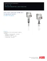
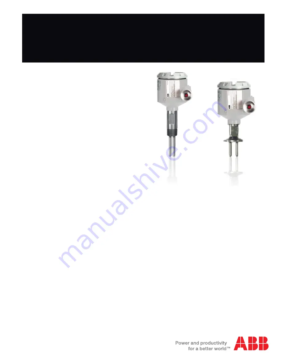
background image

TX and TS

Thermal Dispersion Level Switches

Operating instruction manual OI/TX-EN Rev. J

Flow, level, granular solids and 

temperature switch

K-TEK Products

Introduction

This operating instruction manual provides the following 
information:


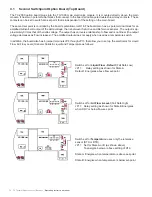
Calibration / set point procedure - see page 5


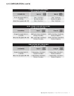
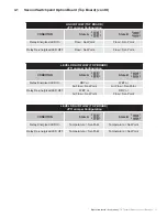
Configuration - see page 7


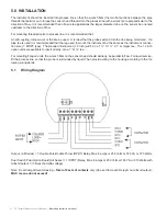
Installation instructions - see page 12


Troubleshooting - see page 18

Summary of Contents for TS series

Page 1: ...ev J Flow level granular solids and temperature switch K TEK Products Introduction This operating instruction manual provides the following information Calibration set point procedure see page 5 Configuration see page 7 Installation instructions see page 12 Troubleshooting see page 18 ...

Page 2: ... Level Operation 13 5 3 Installation for Flow Rates Minimum and Maximum 13 5 4 Installation for Remote Electronics 14 5 5 Installation Setup 15 6 0 Flow Rate Detection 16 7 0 INTERFACE DETECTION 16 8 0 TEMPERATURE SWITCH OPTION 17 9 0 TROUBLESHOOTING 18 9 1 Voltage Resistance mesurments and Jumper Settings Main Board 18 9 2 Procedure for Measuring Voltage to the Sensor Using DVM with power applied...

Page 3: ... against the probes the molecules of the medium absorb more heat from the active sensor and the voltage differential begins to drop or as the flow rate increases the voltage differential will decrease inverse relationship This is the basic principal behind thermal dispersion which allows the configuration of the instrument to trip on flow level or temperature to a set point or a combination of set...

Page 4: ...rol system If fail safe is to be incorporated the output relay and green LED should be energized at what is determined as the normal condition JP3 jumpers are used to determine the relay action vs the normal process condition See the table on page 6 4 JP3 jumpers can be either in a vertical position State A or a horizontal position State B see page 6 Failsafe State required A or B Setting JP3 Jump...

Page 5: ...lower values 3 1 Calibrate from HIGH TC Thermal Conductivity process conditions as follows JP3 State A Green LED output relay energized at NORMAL condition High Thermal Conductivity low differential temperature conditions at the sensors high level level above sensor flow above setpoint see table page 6 Notes 1 If the TX switch is operated in State A the TX switch should be adjusted calibrated in t...

Page 6: ...Thermal Conductivity process condition high level level above sensor high flow condition at the sensor Green LED and output relay will be de energized after calibration adjust ments 2 Allow 5 minutes minimum time for switch temperature to stabilize 3 Adjust R18 see drawing page 5 as follows A If LED is On slowly turn R18 clockwise CW until the green LED turns OFF B If LED is Off slowly turn R18 co...

Page 7: ...r a combination of level and temperature or flow and temperature with the dual switch point option With the dual switch point option board the flow rate of a process can be monitored with the millivolt output approximately 1 volt to 3 millivolts The millivolt output has an inverse relationship to flow In this configuration the unit is two switches contained in one housing The output of basic unit ...

Page 8: ...Switch set for Level or Air Flow Fail Safe High Level or High Flow JP3 Relay set for State B Energizes when dry or below flow set point above setting of R18 Two Jumpers x 2mm Switch set for Temperature uses only the reference sensor STS or RTD JP3 Set for State A or B as shown To energize below or above setting of R18 State A Energize when temperature is below set point State B Energize when tempe...

Page 9: ...ergized LED On Fail Safe WET or Air Flow Set Point Normal Condition DRY or Air Flow Set Point Normal Condition Relay De energized LED OFF DRY or Air Flow Set Point Normal Condition WET or Air Flow Set Point Normal Condition TEMPERATURE BOTTOM BOARD JP3 Jumper Configuration Condition State A State B Relay Energized LED On Fail Safe Temperature Set Point Normal Condition Temperature Set Point Normal...

Page 10: ... the delta voltage The output has an inverse relationship to flow and is not linear the output voltage decreases as flow increases The amplified output does not apply when used as a temperature switch In addition the board also has 6 jumper terminals JP8 through JP13 that allow you to set up the electronics for Liquid Flow Air Flow Level Granular Solids Liquid and Temperature as follows Switch set...

Page 11: ...ration Condition State A State B Relay Energized LED On DRY or Air Flow Set Point WET or Air Flow Set Point Relay De energized LED OFF WET or Air Flow Set Point DRY or Flow Set Point LEVEL OR AIR FLOW TOP BOARD JP11 Jumper Configuration Condition State A State B Relay Energized LED On Temperature Set Point Temperature Set Point Relay De energized LED OFF Temperature Set Point Temperature Set Point...

Page 12: ...e leg used to mount the instrument be the same as the instrument connec tion size 1 MNPT type The standard instrument 1 8 inch will fit in a 1 X 1 X 1 or larger tee The 1 2 inch option units are available to insert directly into a 1 or tee For mounting flanged units the wrench flats on the sensor head should similarly be parallel to flow For liquid service fill the process line so that the probe i...

Page 13: ... and Maximum This switch can be also be configured to detect between a minimum or a maximum flow rate or a minimum maximum temperature With the dual circuit board option the unit can also detect a flow rate and temperature in one housing The output relays would be wired in series PROCEDURE FOR LIQUID LEVEL OPERATION A The instrument detects the thermal conductivity of the medium surrounding the pr...

Page 14: ...mperature that exceeds the maximum operating temperature 140 F or 65 C of the electronics module The remote housing simply contains a terminal block interface for a cable which connects to another housing containing the electronics that is located in a more suitable environment The cable can be one of two types each of which is designed for a specific temperature range See Ap pendix A ...

Page 15: ...nit in a tee the tee size should be the same size as the line or smaller A larger diameter tee will allow the water to expand and cause false trip to occur because of vortices and or eddy currents The switch must be installed as show above in a flow application Rotating the switch from this position will cause the switch to respond slower and will alter a calibrated set point 5 5 Installation Setu...

Page 16: ...onse time is needed the TQ version may be the solution For small flow rates the IX or IM in line unit would be the option The delta voltage will decrease With the dual switch point top board the delta voltage can be monitored and or plotted to determine flow rate inverse relationship and non linear The voltage output can not be used with temperature This switch can be configured to detect the inte...

Page 17: ... 40 50 60 70 80 90 300 275 4 297 9 320 3 342 7 365 387 4 409 6 431 8 450 476 2 200 498 3 520 4 542 4 564 4 586 3 608 2 630 1 651 9 673 7 695 5 100 717 2 738 8 760 5 782 1 803 6 825 1 846 6 868 0 889 4 910 7 0 932 1 953 3 974 5 995 7 1016 9 1038 0 1059 1 1080 1 1101 1 1122 0 100 1142 9 1163 8 1184 6 1205 4 1226 2 1246 9 1267 5 1288 2 1308 8 1329 3 200 1349 8 1370 3 1390 7 1411 1 1431 4 1451 8 1472 ...

Page 18: ...odel 141mV TQ Model 140mV TS Model 460mV IX Model 110mV Water TX HO Model 30mV H1 H2 Model 10mV TQ Model 25mV TS Model 90mV IX Model 15mV 9 2 1 With power disconnected measure resistance of Heater and Sensors P2 Sensor Plug disconnected Female Connector Pin 2 Black Wire Common to RTD Pins 4 5 172 ohms on the TX only Red Wires 470 ohms on the TS TQ IX and IM Red Wires Pins 1 2 1K ohm ambient temper...

Page 19: ...Operating instruction manual TX Thermal Disperson Level Switches 19 10 0 APPENDIX A Instrument Rangeability 10 1 TX Series 10 2 IX Series ...

Page 20: ...evel Switches Operating instruction manual 11 0 APPENDIX B Conversion Table Examples Example 1 100 CFM in 4 line 100 x 1884 18 84 F P S Example 2 10 G P M in 3 line 10 x 0434 434 F P S Test Conditions 60 F 14 7PSIA SCH 40 Line ...

Page 21: ...ption H1 320 F 500 F RED RED WHT BLK GRN SEE WIRE MARKERS Special Temperature Range Option H2 100 F 900 F TERMINAL NUMBER 1 2 3 4 5 HTR HTR ACT COM REF Integral Electronics RED RED YEL BLK GRN Remote Electronics Type J Cable PVC BLUE WHITE DRAIN WHT BLK GRN Remote Electronics Type F Cable Teflon RED OF PAIR 1 RED FOIL BLACK OF PAIR 1 DRAIN OF PAIR 3 WHITE OF PAIR 2 GRN FOIL BLACKS OF PAIRS 2 3 GRE...

Page 22: ...13 0 APPENDIX D TX Heating vs Dispersion Above is a graph of the model TX probe The longer line depicts the time response of the RTD by internal heating The shorter line depicts the delta voltage or delta temperature or delta resistance decreasing when immersed in water ...

Page 23: ...ch were not the result of either alterations misuse abuse improper or inadequate adjustments applications or servicing of the product ABB s warranty does not include onsite repair or services Field service rates can be supplied on request If a product is believed to be defective the original purchaser shall notify ABB and request a Returned Material Authorization before returning the material to A...

Page 24: ...evel Switches Operating instruction manual 15 0 CUSTOMER SUPPORT ABB USA Canada International 18321 Swamp Road Prairieville LA 70769 USA Tel 1 225 673 6100 Fax 1 225 673 2525 Email service ktekcorp com Website www abb com level ...

Page 25: ...y Data Sheets MSDS and decontamination tags by affixing these documents in close proximity to the shipment label for identification purposes January 18 2006 Return Authorization Form Customer Date Contact Name Product Contact Email Serial No Contact Phone Job No Contact Fax Service Rep Completed by Customer Reason Problem Found None Action None Requested Is expedited return shipping requested If y...

Page 26: ...26 TX Thermal Disperson Level Switches Operating instruction manual ...

Page 27: ...Operating instruction manual TX Thermal Disperson Level Switches 27 ...

Page 28: ...ible lack of information in this document We reserve all rights in this document and in the subject matter and illustrations contained therein Any reproduction disclosure to third parties or utilization of its contents in whole or in parts is forbidden without prior written consent of ABB Copyright 2012 ABB All rights reserved ABB Inc 18321 Swamp Road Prairieville LA 70769 USA Phone 1 225 673 6100...

Reviews: