background image

Contents 


4 TTF300 

OI/TTF300-EN 

7.1


Configuration types ......................................................................................................................................34


7.1.1


HART communication ...........................................................................................................................34


7.1.2


Configuration via the LC display with control buttons ...........................................................................36


7.1.3


Menu navigation....................................................................................................................................37


7.1.4


Example of configuration changes........................................................................................................39


7.2


Activating write protection ............................................................................................................................40


7.3


Deactivating write protection ........................................................................................................................40


8


2-sensor input functionality / Dual sensor mode....................................................................................44


8.1


2-HART measurement signals .....................................................................................................................44


8.2


Sensor redundancy / Sensor backup ...........................................................................................................44


8.3


Sensor drift detection ...................................................................................................................................46


8.4


Sensor error adjustment (TTF300 DTM: Adjust function / HMI LC display: Calibrate function) ..................48


8.5


D/A analog output compensation (4 and 20 mA trim) ..................................................................................49


8.6


HART variable assignment...........................................................................................................................49


8.7


Communication / HART tag / Device address..............................................................................................50


8.8


Description of parameters ............................................................................................................................51


8.8.1


Factory settings.....................................................................................................................................58


9


Error messages ..........................................................................................................................................59


10


Additional TTF300 DTM diagnostic information .....................................................................................62


10.1


Long-term monitoring ...................................................................................................................................62


10.2


Operating hour statistics...............................................................................................................................62


11


Maintenance / Repair .................................................................................................................................63


11.1


General information......................................................................................................................................63


11.2


Cleaning .......................................................................................................................................................63


12


Ex relevant specifications .........................................................................................................................64


12.1


TTF300-E1XX, intrinsic safety ATEX ...........................................................................................................64


12.2


TTF300-H1XX, intrinsic safety IECEx ..........................................................................................................64


12.3


Safety specifications for Intrinsic Safety ATEX / IECEx...............................................................................64


12.4


TTF300-E5XX, non-sparking ATEX + dust explosion protection.................................................................65


12.5


TTF300-D1XX, dust explosion protection ....................................................................................................65


12.6


TTF300-D2XX, dust explosion prot intrinsic safety .........................................................................65


12.7


TTF300-E3XX, flameproof enclosure...........................................................................................................65


12.8


TTF300-E4XX, flameproof enc intrinsic safety................................................................................65


12.9


TTF300-L1XX, intrinsically safe FM .............................................................................................................65


12.10


TTF300-L2XX, non-incendive FM ................................................................................................................65


12.11


TTF300-L3XX, explosion proof FM ..............................................................................................................65


12.12


TTF300-L7XX, explosion proof + Intrinsically Safe FM................................................................................65


12.13


TTF300-R1XX, intrinsically safe CSA ..........................................................................................................65


12.14


TTF300-R2XX, non-incendive CSA .............................................................................................................65


12.15


TTF300-R3XX, explosion proof CSA ...........................................................................................................65


12.16


TTF300-R7XX, explosion proof + Intrinsically Safe CSA.............................................................................65


13


Specifications .............................................................................................................................................66


13.1


Input..............................................................................................................................................................66


13.1.1


Resistance thermometers / Resistors ...................................................................................................66


13.1.2


Thermocouples / Voltages ....................................................................................................................66


13.1.3


Functionality ..........................................................................................................................................66


13.2


Output...........................................................................................................................................................66


13.3


Power supply (polarity safe) .........................................................................................................................67


Summary of Contents for TTF300

Page 1: ...Operating Instruction OI TTF300 EN Field mounted Temperature Transmitter TTF300...

Page 2: ...05 555 Customer service center Phone 49 180 5 222 580 Fax 49 621 381 931 29031 automation service de abb com Copyright 2010 by ABB Automation Products GmbH Subject to changes without notice This docum...

Page 3: ...on 12 2 5 Ex relevant specifications 12 3 Design and function 13 4 Mounting 14 4 1 Installation options 14 4 1 1 Wall installation 14 4 1 2 Pipe installation 15 4 2 Installing the optional LCD display...

Page 4: ...ntenance Repair 63 11 1 General information 63 11 2 Cleaning 63 12 Ex relevant specifications 64 12 1 TTF300 E1XX intrinsic safety ATEX 64 12 2 TTF300 H1XX intrinsic safety IECEx 64 12 3 Safety specif...

Page 5: ...1 Features 71 15 2 Specifications 71 15 3 Type B LCD configuration function 71 15 4 Ex relevant specifications 71 15 4 1 Intrinsic Safety ATEX IECEx 71 15 4 2 Safety specifications for intrinsic safet...

Page 6: ...y in a safe maintenance free state The information in the manual must be observed and followed in order to maintain this state throughout the period of operation Modifications and repairs to the produ...

Page 7: ...coming into contact with the materials to be measured ABB Automation Products GmbH will gladly support you in selecting the materials but cannot accept any liability in doing so The operators must str...

Page 8: ...esult in death or severe injury WARNING Bodily injury This symbol in conjunction with the signal word Warning indicates a potential electrical hazard Failure to observe this safety information may res...

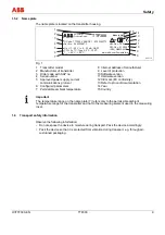
Page 9: ...rent communications protocol 6 Configured parameters 7 Permissible ambient temperature 8 Internet address of manufacturer 9 Level of protection 10 Software version 11 Hardware version 12 CE mark EC co...

Page 10: ...pply voltage corresponds with the voltage of the transmitter When there is a chance that safe operation is no longer possible put the device out of operation and secure against unintended operation Ch...

Page 11: ...ay be disposed of at municipal garbage facilities Proper disposal prevents negative effects on people and the environment and supports the reuse of valuable raw materials If it is not possible to disp...

Page 12: ...on of the operating instructions titled Ex relevant specifications 2 2 Grounding If for functional reasons the intrinsically safe circuit needs to be grounded by means of connection to the equipotenti...

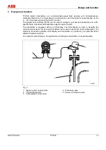
Page 13: ...basis Handheld terminals also support communication The transmitter is equipped with an LCD display The LCD display is used to visualize the current process data The four control buttons can be used t...

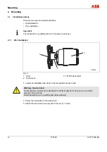
Page 14: ...installation A00089 1 3 2 Fig 3 1 Wall 2 Wall mount 3 TTF300 transmitter 1 Locate an installation site close to the temperature sensor head Warning General risks The transmitter can fall and be damag...

Page 15: ...TF300 3 Transmitter 1 Locate an installation site on a pipe close to the temperature sensor head Important The pipe mount can be attached to a pipe with a maximum diameter of 2 5 inch 2 Screw the tran...

Page 16: ...ing cover for the transmitter 2 Carefully remove the LCD display from the inset for the transmitter The LCD display is held firmly in place You may have to use the tip of a screwdriver to pry the LCD...

Page 17: ...ith the specifications on the name plate and the technical specifications see Technical Specifications chapter and or data sheet Important The electrical connection is carried out with the transmitter...

Page 18: ...ion 8 DIP switch 1 on hardware write protection is enabled DIP switch 2 no function 9 Interface for LC display 10 11 Signal power supply connection 11 42 VDC 4 20 mA 11 30 VDC 4 20 mA Ex 1 Route the p...

Page 19: ...hen connecting the transmitter and measuring inset sensor make sure for thermocouple sensors that the material of the sensor connecting cable corresponds to the thermocouple model 1 Look for the conne...

Page 20: ...used acc to manufacturer s data sheet or Ex certificate The cable gland used must be approved for the cable diameter IP protection class For tightening torque observe information in data sheet operati...

Page 21: ...th plastic sleeves and suitable outer diameters All applicable requirements as stipulated by EN 60079 14 must be observed Installation instructions The rings will harden at low temperatures To make th...

Page 22: ...n 2 Cables must be protected against extreme mechanical loads caused by tension torsion crushing etc Even under operating conditions it must be ensured that the cable entry remains hermetically sealed...

Page 23: ...wo wire circuit 1 Sensor backup redundancy sensor drift monitoring mean measurement or differential measurement Thermocouple voltage and resistance thermometer RTD thermocouple combinations A00245 7 6...

Page 24: ...ltage of transmitter refer to technical data for transmitter USmin Minimum supply voltage of power supply SPS input RLtg Line resistance between transmitter and power supply For HART functionality use...

Page 25: ...ower supply SPS input with supply Adding resistance R250 increases the minimum supply voltage UMmin USmin 0 02A x RLtg R250 Where UMmin Minimum operating voltage of transmitter refer to technical data...

Page 26: ...values are to be used as the basis for the prototype test certificates of the apparatuses devices including capacitance and inductivity values of the wires The proof of the intrinsic safety is given i...

Page 27: ...a sheet 5 5 2 1 Zone 0 Transmitter design II 1 G EEx ia IIC T6 Zone 0 Ex Zone 0 Safe area B C ia A00126 ia J A D ia Fig 12 A Sensor B Transmitter TTF300 C Power supply EEx ia D Interface for LC displa...

Page 28: ...J A D ia Fig 13 A Sensor B Transmitter TTF300 C Power supply EEx ib D Interface for LC display The input for the repeater power supply must be designed to EEx ib as a minimum The user must ensure that...

Page 29: ...d to EEx ib as a minimum The user must ensure that sensor instrumentation meets the requirements of applicable Ex standards It can be installed in Zone 0 Zone 1 or Zone 20 For Zone 0 and Zone 20 the c...

Page 30: ...rotection zone 20 Safety area B C A00130 J A D E Fig 16 A Sensor B Transmitter TTF300 C Power supply D Fuse 32 mA E Interface for LC display The electric circuit of the transmitter must be limited by...

Page 31: ...Explosion protection zone 0 Explosion protection zone 20 Safety area B C A00131 J A ia ia D ia Fig 17 A Sensor B Transmitter TTF300 C Power supply D Interface for LC display When using the sensor in z...

Page 32: ...rotection zone 1 Safety area B C A00132 J A E D Fig 18 A Sensor B TTF300 transmitter in Ex d housing C Power supply D Fuse 32 mA E Interface for LC display To achieve the flameproof protection proper...

Page 33: ...housing C Power supply D Interface for LC display To achieve the flameproof protection proper mounting of a specially certified cable gland that complies with the standards and relevant Ex designation...

Page 34: ...n software Via DTM in FDT 1 2 frame applications Configuration via fieldbus PROFIBUS if the superordinate remote I O system is HART enabled e g ABB S800 or S900 If necessary Fig 20 1 Handheld terminal...

Page 35: ...to be realized according to the figure in the Configuration types paragraph Important The connection of the test tips is performed without polarity Thus it does not make a difference which test tip is...

Page 36: ...low the LC display on the front side of the housing The control buttons and the LC display are in a protected location under the housing cover with inspection glass The housing cover must be unscrewed...

Page 37: ...em The meanings of these control buttons are displayed at the bottom of the LC display above the respective control button The following functions are possible Functions of control button Meaning Exit...

Page 38: ...lected if the menu contains submenus You can only then select a parameter when the corresponding submenu contains configurable parameters e g Sensor Type 7 1 3 3 Configuring a parameter value 1 If a p...

Page 39: ...e type K Measuring range 0 1000 C Reference point internal Fault signaling Override 22 mA Damping Off 0s Write Protection activated Procedure Fig 25 1 Press the 4 control button to call up the main me...

Page 40: ...cting the digit position by using the 1 control button with the control button 2 or 3 before or after the configurable digits 0 to 9 7 2 Activating write protection 1 Confirm Config Device via control...

Page 41: ...on Main menu Submenu 1 Submenu 2 Device Config Write Protect Yes Set Password 0110 No Set Password 0110 Input Sensor 1 Sensortype R Connection 2 wire Resistance Thermocouple RJ ext RJ Temperature Inpu...

Page 42: ...nd Damping Factory Reset Device info Device Type Serialnumber Softwareversion Hardwareversion HART Tag HART Descriptor Operating Time Display Main Operator View Process Variable Sensor 1 Sensor 2 Elec...

Page 43: ...ing Upscale Downscale Communication HART Tag Address Multidrop HART Burstmode Status Command Calibrate Measured range Apply Lower Range Apply Upper Range Analog Output Trim 4 mA Trim 20 mA Diagnostics...

Page 44: ...th Namur NE 107 Maintenance required Sensor wire break If redundant sensor 2 fails a HART signal diagnostic notification is generated To minimize the effect on the output signal and increase accuracy...

Page 45: ...ff On Configurable pulse width Continuous pulse 5 Wire break temperature characteristic 2 Example If a pulse width of 10 seconds is set the normal temperature signal of 4 20 mA is found at the output...

Page 46: ...missible sensor deviation must be configured e g max 1 C 33 8 F Based on possible marginally different sensor response times a limit must subsequently be set during which time the sensor deviation mus...

Page 47: ...ling during sensor drift overshoot 1 Temperature characteristic for sensor 1 2 Temperature characteristic for sensor 2 3 4 20 mA output signal 4 Maximum sensor drift differential e g 1 C 5 Alarm pulse...

Page 48: ...lates the temperature deviation resulting from the sensor error During single point adjustment the temperature deviation calculated results in an offset shift of the linear characteristic output by th...

Page 49: ...Simulate the LRL or 4 000 mA 16 A in D A analog output compensation mode using sensor simulation Thereafter enter the iteratively measured current at which the superordinate system displays exactly 4...

Page 50: ...switches to HART multidrop mode This operating mode enables users to connect up to 15 devices in parallel to a power supply In multidrop mode an analog output signal that matches the process temperat...

Page 51: ...E IEC584 Thermocouple type J IEC584 Thermocouple type N IEC584 Thermocouple type R IEC584 Thermocouple type S IEC584 Thermocouple type T IEC584 Thermocouple type L DIN43710 Thermovoltage 125 125 mV T...

Page 52: ...rence Point Device Device Input Sensor 1 Reference Point internal without externally fixed Check safety function Sensor 1 Reference point ext Relevant for external reference point information on const...

Page 53: ...temperature Device Configuration Sensor 1 Reference Point Device Setup Input Sensor 2 Reference Point Like sensor 1 Safety function relevant and requires check of following input output assignments S...

Page 54: ...independent sensors 1 and 2 is mapped to the 4 20 mA analog output according to the parametrized measuring range Device Configuration Measurement Type Primary Variable PV Device Setup Input output as...

Page 55: ...al damping value Device Parametrize Voltage Output Damping Device Setup Damping 0 100 s Depending on sensor type Factory reset Configuration data is reset to factory settings for Pt100 3 wire 0 100 C...

Page 56: ...Maintenance Adjust Calibrate Measuring Range Trim low or Set Lower Range Value ok Check safety function Set measurement end Temperature correction for specified simul Sensor measurement value at desir...

Page 57: ...s C F mV Ohm Check safety function Drift detection Sensor drift Limit time period Time period during which the max sensor differential must be overshot before sensor drift signaling occurs Device Para...

Page 58: ...ng Write Protect No Sensortype Pt100 IEC751 R Connection 3 wires Measured Range Begin 0 Measured Range End 100 Unit C Device Config Input Sensor 1 Damping Off Process Alarm Fault signaling Override 22...

Page 59: ...tory settings notify service of error message Device I 7 HMI inserted Status info no error Device I 8 Device write protected Status info no error Device I 9 EEPROM busy Status info no error Device F 1...

Page 60: ...limits Sensor 2 I 57 Status info Status info no error Sensor 2 I 58 Status info Status info no error Application F 65 Configuration defective Check configuration A Incorrect device B Measuring span i...

Page 61: ...A Above sensor range Measuring span is too small Application S 77 Limit HIGH HIGH Upper limit value Alarm Application S 78 Limit LOW LOW Lower limit value Alarm Application S 79 Limit HIGH Upper limit...

Page 62: ...s subjected to This value cannot be reset Maximum value sensor 1 2 Highest reading at sensor 1 or 2 When changing the sensor type e g Pt100 to thermocouple type K the value is reset automatically Mini...

Page 63: ...ance is required No on site repair or replacement of electronic parts is planned Warning Risk of explosion Faulty transmitters may not be placed into operation by the user Repairs must be performed in...

Page 64: ...ce category 2 use T6 50 44 C 58 111 2 F 50 56 C 58 132 8 F T5 50 56 C 58 132 8 F 50 71 C 58 159 8 F T4 T3 T2 T1 50 60 C 58 140 0 F 50 85 C 58 185 0 F hallo Protection type intrinsic safety Ex ia IIC P...

Page 65: ...II 2G EEx d IIC T6 II 1G EEx ia IIC T6 EC prototype test certificate PTB 99 ATEX 1144 EC prototype test certificate PTB 05 ATEX 2017 X 12 9 TTF300 L1XX intrinsically safe FM Class I Div 1 2 Groups A...

Page 66: ...dance with ASTM E 988 Voltages 125 125 mV 125 1 100 mV Connecting cable Maximum sensor line resistance RW for each line 1 5 k total 3 k Sensor wire break monitoring in accordance with NE 89 Pulsed wit...

Page 67: ...ual ripple for supply voltage Max permissible ripple for supply voltage during communication in accordance with HART FSK Physical Layer specification version 8 1 08 1999 Section 8 1 Undervoltage detec...

Page 68: ...class Cx 40 85 C 40 185 F at 5 95 relative humidity DIN EN 60654 1 Max permissible humidity 100 relative humidity IEC 60068 2 30 Vibration resistance 10 2 000 Hz at 5 g in acc with IEC 60068 2 6 duri...

Page 69: ...60 250 C 60 250 C 60 250 C 60 250 C 76 482 F 76 482 F 76 482 F 76 482 F 10 C 10 C 10 C 10 C 18 F 18 F 18 F 18 F 0 16 C 0 08 C 0 08 C 0 08 C 0 29 F 0 14 F 0 14 F 0 14 F 0 05 0 05 0 05 0 05 Cu10 Cu100...

Page 70: ...C 0 014 F 0 003 Pt100 IEC JIS MIL 0 004 C 0 007 F 0 003 Pt200 IEC MIL 0 02 C 0 036 F 0 003 Pt1000 IEC MIL 0 004 C 0 007 F 0 003 Ni50 DIN 43760 0 008 C 0 014 F 0 003 Ni100 DIN 43760 0 004 C 0 007 F 0...

Page 71: ...2 Scroll back 3 Scroll forward 4 Select 1 Additional mechanical protection is required for this range 15 3 Type B LCD configuration function All parameters configurable sensor type sensor circuit mea...

Page 72: ...T4 Tamb 85 C Ui Vmax 9V Ii Imax 65 2 mA Pi 101 mW Ci 0 4 F Li 0 Control Drawing SAP_214 751 15 4 5 Intrinsically Safe CSA I S Class I Div 1 and Div 2 Group A B C D or I S Zone 0 Ex ia IIC T Temp Ident...

Page 73: ...ter in your possession meets the requirements of the following European directives EMC directive 2004 108 EC ATEX directive 94 9 EC Explosion Protection Identification for intended use in potentially...

Page 74: ...Appendix 74 TTF300 OI TTF300 EN...

Page 75: ...one Fax E mail Device details Type Serial no Reason for the return description of the defect Was this device used in conjunction with substances which pose a threat or risk to health F Yes F No If yes...

Page 76: ...30 E EEx i 27 Electrical connections 23 44 Electrical interconnection 26 Error messages 46 59 Ex relevant specifications 71 Ex relevant specifications 12 64 Example of configuration changes 39 F Facto...

Page 77: ...Sensor input functionality Dual sensor mode 44 Sensor redundancy Sensor backup 44 Sensor short circuit 66 Sensor wire break 66 Simulation mode 66 Specifications 6 66 71 T Target groups and qualificat...

Page 78: ...ed herein without notice Printed in the Fed Rep of Germany 04 2010 ABB 2010 3KXT221001R4201 OI TTF300 EN Rev B ABB Limited Salterbeck Trading Estate Workington Cumbria CA14 5DS UK Tel 44 0 1946 830 61...

Reviews: