Index
76 TTF300
OI/TTF300-EN
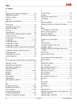
17 Index
Change from one to two columns
A
Additional DTM diagnostic information ...................62
Additional documents ..............................................73
Ambient conditions ..................................................68
Appendix ..................................................................73
Approvals and certifications.....................................73
C
Cable glands ............................................................20
Changing the sensor type........................................62
Claims for damages.................................................10
Cleaning...................................................................63
Commissioning ........................................................34
Communication / HART tag / Device address .........50
Conductor material ..................................................17
Configurable error current signal .............................66
Configuration......................................................34, 35
Configuration types..................................................34
Configuration via DTM .............................................35
Configuration via EDD .............................................35
Configuration via the LC display with control buttons
.............................................................................36
Configuration with the handheld terminal ................35
Connecting cable .....................................................66
Contamination of devices ........................................75
Corrosion detection..................................................66
D
D/A analog output compensation (4 and 20 mA trim)
.............................................................................49
Damages in transit...................................................10
Deactivating write protection....................................40
Description of parameters........................................51
Design and function .................................................13
Diagnostics ........................................................36, 44
Disposal ...................................................................11
Disposal ...................................................................11
Drag indicator...........................................................62
Drift detection...........................................................46
Dust-explosion protection ........................................30
E
EEx i.........................................................................27
Electrical connections ........................................23, 44
Electrical interconnection.........................................26
Error messages..................................................46, 59
Ex relevant specifications ........................................71
Ex relevant specifications ..................................12, 64
Example of configuration changes...........................39
F
Factory settings........................................................58
Features...................................................................71
Flameproof protection Zone 1..................................32
Functionality.............................................................66
G
General information ...........................................63, 68
General information and notes for the reader............6
H
HART
Configuration changed flag ..................................62
HART variable assignment ......................................49
Hazardous materials................................................10
Highest and lowest values .......................................62
I
Induced current consumption ..................................66
Input .........................................................................66
Input resistance........................................................66
Installation in explosion risk area.............................27
Installation options ...................................................14
Installing the optional LCD display with control
buttons..................................................................16
Intended use ..............................................................6
Internal reference point............................................66
L
Lowest detected internal temperature .....................62
Lowest reading.........................................................62
M
Maintenance / Repair...............................................63
Max. elec. temp........................................................62
Max. reading for sensors 1-2 ...................................62
Maximum output current ..........................................66
Measurement current...............................................66
Menu structure .........................................................41
Min. elec. temp.........................................................62
Min. reading for sensors 1-2 ....................................62
Mounting ............................................................14, 15
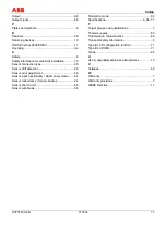
N
Name plate.................................................................9
Navigation ................................................................37
Note symbols .............................................................8
O
Operating Hours.......................................................62
Operating hours per electronic unit temperature .....62
Operating influences................................................70
Operating safety information....................................10

