background image

Contents 


4 TTF350 

OI/TTF350-EN 

7


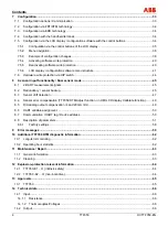
Configuration .....................................................................................................................................................33


7.1


Configuration options / Communication .......................................................................................................33


7.2


Configuration via FDT/DTM technology .......................................................................................................34


7.3


Configuration via EDD technology ...............................................................................................................34


7.4


Configuration with the handheld terminal.....................................................................................................34


7.5


Configuration via the LCD display / configuration software with the control buttons ...................................34


7.5.1


Configuration via the control buttons of the LCD display......................................................................35


7.5.2


Menu navigation....................................................................................................................................36


7.5.3


Example of configuration changes........................................................................................................38


7.5.4


Activating software write protection ......................................................................................................40


7.5.5


Deactivating software write protection ..................................................................................................40


7.5.6


LCD display / configuration software menu structure ...........................................................................41


7.6


Hardware write protection via DIP switch.....................................................................................................44


8


2-sensor input functionality / Dual sensor mode...........................................................................................45


8.1


2-HART measurement signals .....................................................................................................................45


8.2


Redundancy / sensor backup.......................................................................................................................45


8.3


Sensor drift detection ...................................................................................................................................47


8.4


Sensor error compensation (TTF350 DTM Adjust function / in HMI LCD display Calibrate function).........49


8.5


D/A analog output compensation (4 and 20 mA trim) ..................................................................................49


8.6


HART variable assignment...........................................................................................................................50


8.7


Communication / HART tag / Device address..............................................................................................50


8.8


Description of parameters ............................................................................................................................51


8.8.1


Factory settings.....................................................................................................................................58


9


Error messages .................................................................................................................................................59


10


Additional TTF350 DTM diagnostic information ............................................................................................62


10.1


Long-term monitoring ...................................................................................................................................62


10.2


Operating hour statistics...............................................................................................................................62


11


Maintenance / Repair.........................................................................................................................................63


11.1


General information......................................................................................................................................63


11.2


Cleaning .......................................................................................................................................................63


12


Explosion-protection relevant information.....................................................................................................64


12.1


TTF350-E1 .. H: (intrinsic safety) .................................................................................................................64


12.2


TTF350 -E2 .. H: (non-incendive).................................................................................................................64


13


Approvals ...........................................................................................................................................................65


13.1


TTF350.........................................................................................................................................................65


14


Technical data....................................................................................................................................................66


 

14.1


Input..............................................................................................................................................................66


14.1.1


Resistance.............................................................................................................................................66


14.1.2


Thermocouples/Voltages ......................................................................................................................66
 

14.2


Output...........................................................................................................................................................66
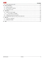
 

Summary of Contents for TTF350

Page 1: ...Operating Instructions OI TTF350 EN Field mounted Temperature Transmitters TTF350...

Page 2: ...u Germany Tel 49 551 905 534 Fax 49 551 905 555 CCC support deapr de abb com Copyright 2007 by ABB Automation Products GmbH Subject to change without notice This document is protected by copyright It...

Page 3: ...requiring ignition protection 11 2 1 Approvals 11 2 2 Ground 11 2 3 Interconnection 11 2 4 Configuration 11 2 5 Explosion protection relevant information 11 3 Design and function 12 4 Installation 13...

Page 4: ...onality Dual sensor mode 45 8 1 2 HART measurement signals 45 8 2 Redundancy sensor backup 45 8 3 Sensor drift detection 47 8 4 Sensor error compensation TTF350 DTM Adjust function in HMI LCD display...

Page 5: ...ompatibility 67 15 3 Interference immunity 67 16 LCD display 68 16 1 Features of the LCD display 68 16 1 1 Technical data of LCD display 68 16 2 Configuration function of LCD display 68 16 3 LCD displ...

Page 6: ...rds and the safe and trouble free operation of the device 1 2 Intended use This device is intended for the following uses To measure the temperature of fluid pulpy or pasty substances and gases or res...

Page 7: ...ath or serious injury will result Warning Bodily injury The symbol in conjunction with the Warning message indicates a possibly dangerous situation If it is not avoided death or serious injury could r...

Page 8: ...try Important The temperature range on the model plate 6 refers only to the permissible ambient temperature range for the transmitter and not to the measuring element used in the measuring inset 1 6 O...

Page 9: ...from materials that can be reused by specialized recycling companies 1 9 1 Information on WEEE directive 2002 96 EC Waste Electrical and Electronic Equipment This product solution is not subject to th...

Page 10: ...fil the requirements of the DIN VDE 0106 T 101 basic requirements for secure isolation For secure isolation run the supply lines separated from contact dangerous electrical circuits or additionally is...

Page 11: ...nal reasons the intrinsically safe circuit has to be grounded by connection to the equipotential bonding system it may only be grounded at a single location 2 3 Interconnection If transmitters are ope...

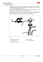
Page 12: ...can be used to configure poll and test transmitters on a PC specific basis Handheld terminals also support communication The transmitter is equipped with an LCD display The LCD display is used to visu...

Page 13: ...49 175 6 89 175 6 89 175 6 89 175 6 89 241 9 49 241 9 49 1 2 3 3 2 1 Fig 3 Dimensions in mm inches 1 Wall 3 Transmitter TTF350 2 Wall mount 1 Locate an installation site close to the temperature senso...

Page 14: ...e temperature sensor head Important The pipe mount can be attached to a pipe with a maximum diameter of 2 max 60 mm 2 Screw the transmitter to the pipe mount 3 Attach the pipe mount securely to the pi...

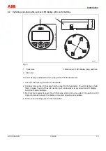
Page 15: ...transmitter 1 Unscrew the housing cover for the transmitter 2 Carefully remove the LCD display from the inset for the transmitter The LCD display is held firmly in place You might have to use the tip...

Page 16: ...h the specifications on the name plate and the technical specifications see Technical Specifications chapter and or data sheet Important The electrical connection is carried out with the transmitter i...

Page 17: ...box of the TTF350 field device 1 6 Sensor connection 7 9 Signal power supply connection 11 42 VDC 4 20 mA 11 30 VDC 4 20 mA Ex 7 Shield 8 Minus 9 Plus 1 Route the power supply cable through the cable...

Page 18: ...ermocouple sensors that the material of the sensor connecting cable corresponds to the thermocouple model 1 Look for the connection type for the selected measuring element in the connection diagrams 2...

Page 19: ...gland used acc to manufacturer s data sheet or Ex certificate The cable gland used must be approved for the cable diameter IP protection class For tightening torque observe information in data sheet o...

Page 20: ...otentiometer 0 500 or 0 5000 1 Potentiometer 4 wire circuit 2 Potentiometer 3 wire circuit 3 Potentiometer 2 wire circuit 4 2 x RTD 3 wire circuit sensor backup redundancy sensor drift monitoring aver...

Page 21: ...erential temperature measurement 12 Thermocouple RTD thermocouples configuration 11 30 Ex 42 VDC 4 20 mA 15 14 13 A00190 5 5 5 4 6 6 6 2 2 3 3 3 1 1 1 6 5 4 3 2 1 PA PA 4 3 1 2 5 6 Fig 9 13 1 x RTD 4...

Page 22: ...ansmitter refer to technical data for transmitter USmin Minimum supply voltage of power supply SPS input RLtg Line resistance between transmitter and power supply For HART functionality use power supp...

Page 23: ...S input with supply Adding resistance R250 increases the minimum supply voltage UMmin USmin 0 02A x RLtg R250 Where UMmin Minimum operating voltage of transmitter refer to technical data for transmitt...

Page 24: ...imit values are to be used as the basis for the prototype test certificates of the apparatuses devices including capacitance and inductivity values of the wires The proof of the intrinsic safety is gi...

Page 25: ...elevant information or the data sheet 5 5 2 1 Zone 0 Transmitter design II 1G EEx ia IIC T6 Zone 0 Explosion protection zone 0 Safety area B C ia A00126 ia J A D ia Fig 13 A Sensor B TTF350 transmitte...

Page 26: ...C ib A00127 ia J A D ia Fig 14 A Sensor B TTF350 transmitter C Power supply EEx ib D HMI interface for LCD display The input for the power supply must be at a minimum in EEx ib design The sensor must...

Page 27: ...A00128 ia J A D ia Fig 15 A Sensor B TTF350 transmitter C Power supply EEx ib D HMI interface for LCD display The input for the power supply must be at a minimum in EEx ib design The sensor must be u...

Page 28: ...tter design II 3G EEx nA II T6 Explosion protection zone 2 Safety area B C A00129 J A D Fig 16 A Sensor B TTF350 transmitter C Power supply D HMI interface for LCD display Ensure that in case of a dis...

Page 29: ...ection zone 20 Safety area B C A00130 J A D E Fig 17 A Sensor B TTF350 transmitter C Power supply D Fuse 32 mA E HMI interface for LCD display The electric circuit of the transmitter must be limited b...

Page 30: ...losion protection zone 0 Explosion protection zone 20 Safety area B C A00131 J A ia ia D ia Fig 18 A Sensor B TTF350 transmitter C Power supply D HMI interface for LCD display When using the sensor in...

Page 31: ...Explosion protection zone 1 Safety area B C A00132 J A E D Fig 19 A Sensor B TTF350 transmitter in Ex d housing C Repeater power supply D Fuse 32 mA E HMI interface for LCD display To achieve the her...

Page 32: ...in Ex d housing C Repeater power supply D HMI interface for LCD display To achieve the hermetically sealed protection class proper mounting of a specially certified cable gland that complies with the...

Page 33: ...C and SmartVision configuration software via DTM in FDT 1 2 network applications Configuration via field bus Profibus if the superordinate I O system is HART enabled e g ABB S800 or S900 if necessary...

Page 34: ...tips of the separate operating control on the contacts in the slotting in front of the and connection terminals 3 Be sure the test terminals are firmly seated 4 The installation is to be realized acco...

Page 35: ...low the LCD display on the front side of the housing The buttons and the LCD display are in a protected location under the housing cover with inspection glass The housing cover must be unscrewed befor...

Page 36: ...s functions assigned to them The meaning of these buttons is displayed below in the LCD display above the respective button The following functions are possible Button functions Meaning Exit Exit menu...

Page 37: ...selected if the menu contains submenus You can only then select a parameter when the corresponding submenu contains configurable parameters e g Sensor Type Configuring a parameter value 1 If a parame...

Page 38: ...Override 22 mA Damping Off 0s Write Protection activated Procedure Fig 26 1 Press the button to call up the main menu 2 Use the 2 and 3 buttons to mark Config Device and confirm via 4 3 Select Input S...

Page 39: ...these via the 2 or 3 buttons Important When changing the LRL or URL use the 1 to select the digit position with the current decimal point The digit position can be changed so that no decimal point app...

Page 40: ...Spaces and the number combination 0110 cannot be entered 4 Write protection YES is displayed Click the 1 button three times to exit the configuration mode and display Reading Display Mode 7 5 5 Deacti...

Page 41: ...ection Main menu Submenu 1 Submenu 2 Config device Write Protection Yes Set Password 0110 No Set Password 0110 Input sensor 1 Sensor type Connection type Line resistance Reference junction Reference p...

Page 42: ...end Damping Factory reset Device info Model Serial Number Software Version Hardware version HART tag HART descriptor Operating Hours Display Display value Process data Sensor 1 Sensor 2 Elec measureme...

Page 43: ...g Override Underdrive Communication HART tag Address Multidrop HART burst mode Status Command Calibration Measuring range Set measurement start Set measurement end Analog output Trim 4 mA Trim 20 mA D...

Page 44: ...evice switch 1 must be in off position After successfully configuring the device it is recommended that you activate hardware write protection by moving the switch to the on position Devices are gener...

Page 45: ...amur NE 107 Maintenance required Sensor wire break If redundant sensor 2 fails a HART signal diagnostic notification is generated To minimize the effect on the output signal and increase accuracy in c...

Page 46: ...4 Alarm pulse Off On Configurable pulse width Continuous pulse 5 Wire break temperature characteristic 2 Example If a pulse rate of 10 seconds is set the normal temperature signal of 4 20 mA is found...

Page 47: ...the sensor deviation must be continuously larger than the max sensor drift differential value defined at max 1 C If the transmitter records a larger sensor deviation during the defined time period a H...

Page 48: ...ignaling during sensor drift overshoot 1 Temperature characteristic for sensor 1 2 Temperature characteristic for sensor 2 3 4 20 mA output signal 4 max sensor drift differential e g 1 C 5 Alarm pulse...

Page 49: ...ffset error can on the other hand be corrected only with a two point adjustment or two point calibration If you enter the temperature value for sensor 1 when adjusting for sensor error on channel 2 th...

Page 50: ...HART device features a configurable 8 digit HART tag Standard devices are come with the HART tag TI XXX When storing HART tags with more than 8 digits in the device use the Report parameter which supp...

Page 51: ...e E IEC584 Thermocouple type J IEC584 Thermocouple type N IEC584 Thermocouple type R IEC584 Thermocouple type S IEC584 Thermocouple type T IEC584 Thermocouple type L DIN43710 Thermovoltage 125 125 mV...

Page 52: ...rence Point Device Device Input Sensor 1 Reference Point internal without externally fixed Check safety function Sensor 1 Reference point ext Relevant for external reference point information on const...

Page 53: ...temperature Device Configuration Sensor 1 Reference Point Device Setup Input Sensor 2 Reference Point Like sensor 1 Safety function relevant and requires check of following input output assignments S...

Page 54: ...o independent sensors 1 and 2 is mapped to the 4 20 mA analog output according to the parametrized measuring range Device Configuration Measurement Type Primary Variable PV Device Setup Input output a...

Page 55: ...nal damping value Device Parametrize Voltage Output Damping Device Setup Damping 0 100 s Depending on sensor type Factory reset Configuration data is reset to factory settings for Pt100 3 wire 0 100 C...

Page 56: ...Maintenance Adjust Calibrate Measuring Range Trim low or Set Lower Range Value ok Check safety function Set measuremen t end Temperature correction for specified simul Sensor measurement value at desi...

Page 57: ...ety function Drift detection Sensor drift Limit time period Time period during which the max sensor differential must be overshot before sensor drift signaling occurs Device Parametrize Limit time per...

Page 58: ...ng Write Protect No Sensortype Pt100 IEC751 R Connection 3 wires Measured Range Begin 0 Measured Range End 100 Unit C Device Config Input Sensor 1 Damping Off Process Alarm Fault signaling Override 22...

Page 59: ...tory settings notify service of error message Device I 7 HMI inserted Status info no error Device I 8 Device write protected Status info no error Device I 9 EEPROM busy Status info no error Device F 1...

Page 60: ...limits Sensor 2 I 57 Status info Status info no error Sensor 2 I 58 Status info Status info no error Application F 65 Configuration defective Check configuration A Incorrect device B Measuring span i...

Page 61: ...A Above sensor range Measuring span is too small Application S 77 Limit HIGH HIGH Upper limit value Alarm Application S 78 Limit LOW LOW Lower limit value Alarm Application S 79 Limit HIGH Upper limit...

Page 62: ...ot be reset Max reading for sensors 1 2 Highest reading at sensor 1 or 2 When changing the sensor type e g Pt100 to thermocouple type K the value is reset automatically Min reading for sensors 1 2 Low...

Page 63: ...nance is required No on site repair or replacement of electronic parts is planned Warning Risk of explosion Faulty transmitters may not be placed into operation by the user Repairs must be performed i...

Page 64: ...ly circuit Measurement current circuit passive transducer RTD Measurement current circuit active transducer RTD Display interface Max voltage Ui 30 V Uo 6 5 V Uo 1 2 V Uo 6 2 V Short circuit current I...

Page 65: ...I 2G EEx d IIC T6 EC prototype test certificate ATEX TTF350 E4 H flameproof protection intrinsic safety Zone 1 Designation Ex mark II 2G EEx d IIC T6 Ex mark II 1G EEx ia IIC T6 EC prototype test cert...

Page 66: ...junction Pt100 DIN IEC 60751 Cl B no jumpers necessary Customer specific curve 32 tie points Resistance measurement up to max 5 k Voltages up to max 1 1 V Sensor matching via Callendar van Dusen coef...

Page 67: ...utput filter Digital filter 1st order 0 100 s 1 depending on sensor type and sensor circuit kj 15 1 Ambient conditions Ambient temperature Standard 40 85 C 40 185 F Optional 50 85 C 58 185 F For use w...

Page 68: ...y All parameters sensor type circuit measuring range leakage current signal etc except table based sensor and freestyle characteristics Callendar van Dusen coefficients warning and alarm limits drift...

Page 69: ...itter Conforms with EMV directive 89 336 EWG Conforms with low voltage directive 73 23 EWG For ignition protection applications Conforms with explosion protection directive 94 9 EC ATEX 95 By placing...

Page 70: ...one Fax E Mail Device details Type Serial no Reason for the return description of the defect Was this device used for working with substances which pose a threat or health risk F Yes F No If yes which...

Page 71: ...osal 9 Drift detection 47 Dust ignition proof 29 E Electrical installation safety information 10 Electrical interconnection 24 Error messages 47 59 Example of configuration changes 38 Explosion protec...

Page 72: ...input functionality Dual sensor mode 45 Sensor short circuit 66 Sensor wire break 66 Simulation mode 66 Startup Operation 33 Symbols and warnings 7 T Technical data 66 Technical limits 6 Terminal con...

Page 73: ......

Page 74: ...ithout notice Printed in the Fed Rep of Germany 08 2007 ABB 2007 3KXT221002R4201 OI TTF350 EN ABB Limited Salterbeck Trading Estate Workington Cumbria CA14 5DS UK Tel 44 0 1946 830 611 Fax 44 0 1946 8...

Reviews: