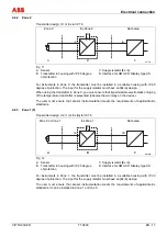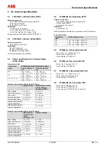
Electrical
connection
CI/TTH200-EN
TTH200
EN - 13
No tools are required to insert the LCD display:
1.
Carefully insert the guide pins for the LCD display in the guide holes of the transmitter
inset. Make sure the black connection socket fits into the terminal on the transmitter inset.
2.
Then press the LCD display in as far as it will go. Make sure that the guide pins and
connection socket are fully inserted.
The position of the LCD display can be adjusted to suit the installation position of the
transmitter, to ensure that the display is legible.
The LCD display has twelve positions that can be set in 30° increments.
Caution - Potential damage to parts
Make sure the flat ribbon cable does not get twisted or torn when rotating the LCD display.
1.
Carefully turn the LCD display to the left to release it from its mount.
2.
Use caution when positioning the LCD display.
3.
Insert the LCD display back into the mount and turn it to the right until it snaps into place.
4 Electrical
connection
Warning - Dangerous electrical current
The relevant guidelines must be observed during electrical installation. Connections must only
be established in a dead-voltage state.
The transmitter has no switch-off elements. Therefore, overvoltage protection devices,
lightning protection, or voltage disconnection options must be provided at the plant.
The power supply and signal are routed in the same line and must be implemented as a SELV
or PELV circuit in accordance with the standard (standard version). For the Ex version, the
guidelines stipulated by the Ex standard must to be adhered to.
A check must be carried out as to whether the existing power supply corresponds to the
specifications both on the name plate and in the technical specifications in the “Technical
specifications" section or the data sheet.
Important
The signal cable wires must be provided with wire end sleeves.
The slotted screws of the connection terminals are tightened with a size 1 screwdriver (3.5 or
4 mm).


