background image

Safety 


8 - EN 

TTH200 

CI/TTH200-EN 


1.6 

Transport safety information  


Observe the following information: 

•  Do not expose the device to moisture during transport. Pack the device accordingly. 

•  Pack the device so that it is protected from vibration during transport, e.g. through air-

cushioned packaging. 


1.7 

Safety information for electrical installation 


The electrical connections may only be performed by authorized specialist personnel according 
to the electrical plans. 

Comply with electrical connection information in the instruction. Otherwise, the electrical 
protection class can be affected. 
The secure separation of contact-dangerous electrical circuits is only ensured when the 
connected devices fulfil the requirements of the  DIN EN 61140  (VDE 0140 Part 1)  (basic 
requirements for secure separation).  
For secure separation, run the supply lines separated from contact-dangerous electrical circuits 
or additionally insulate them. 


1.8 

Safety information for commissioning 


The transmitter is immediately ready for operation after mounting and installation of the 
connections. The parameters are set at the factory. 

The connected lines must be checked for firm seating. Only firmly seated lines ensure full 
functionality. 


1.9 

Operating safety information  


Before switching on, ensure that the specified environmental conditions in the “Technical 
Specifications” chapter and in the data sheet are complied with and that the power supply 
voltage corresponds with the voltage of the transmitter. 

When there is a chance that safe operation is no longer possible, put the device out of operation 
and secure against unintended operation. 
 

Summary of Contents for TTH200

Page 1: ...CI TTH200 EN TTH200 Commissioning Instruction Head mounted Temperature Transmitter TTH200...

Page 2: ...905 534 Fax 49 551 905 555 CCC support deapr de abb com Copyright 2009 by ABB Automation Products GmbH Subject to changes without notice This document is protected by copyright It assists the user in...

Page 3: ...x relevant specifications 9 3 Mounting 10 3 1 Installation options 10 3 1 1 Installation in the cover of the connection head 10 3 1 2 Installation on the measuring inset 11 3 1 3 Installation on a top...

Page 4: ...Incendive CSA 19 6 HMI LCD display type AS 20 6 1 Ex relevant specifications 20 6 1 1 Intrinsic Safety ATEX 20 6 1 2 Intrinsic Safety IECEx 20 6 1 3 Safety specifications for Intrinsic Safety ATEX IEC...

Page 5: ...free state The information in the manual must be observed and followed in order to maintain this state throughout the period of operation Modifications and repairs to the product may only be performed...

Page 6: ...s coming into contact with the materials to be measured ABB Automation Products GmbH will gladly support you in selecting the materials but cannot accept any liability in doing so The operators must s...

Page 7: ...result in death or severe injury WARNING Bodily injury This symbol in conjunction with the signal word Warning indicates a potential electrical hazard Failure to observe this safety information may r...

Page 8: ...e 0 71 C Zone1 40 C 44 C Zone 0 56 C Zone1 0102 HART 13 14 10 8 4 7 5 3 2 12 11 6 9 1 Fig 1 1 Model name 2 Manufacturer of transmitter 3 Country and year of manufacture 4 Order code 5 Serial number 6...

Page 9: ...uirements of the DIN EN 61140 VDE 0140 Part 1 basic requirements for secure separation For secure separation run the supply lines separated from contact dangerous electrical circuits or additionally i...

Page 10: ...protection type of at least IP 20 as per IEC 60529 1989 is achieved 2 3 Electrostatic charging When using the transmitter in Zone 0 please ensure that impermissible electrostatic charging of the TTH20...

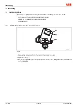
Page 11: ...the connection head without springs directly on the measuring inset spring mounted on a top hat rail 3 1 1 Installation in the cover of the connection head 1 2 3 A00067 Fig 2 1 Release the screw plug...

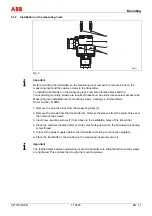
Page 12: ...cs Order number 215882 1 Remove the ceramic block from the measuring inset 3 2 Remove the screws from the transmitter 2 Remove the sleeves from the screw holes and then remove the screws 3 Insert new...

Page 13: ...e LCD display interface the TTH200 can be operated freely with the HMI type AS LCD display enabling process data to be visualized Important The LCD display with HMI type A configuration function used...

Page 14: ...D display back into the mount and turn it to the right until it snaps into place 4 Electrical connection Warning Dangerous electrical current The relevant guidelines must be observed during electrical...

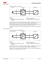
Page 15: ...connection Depending on the sensor model a variety of conductor materials can be used for sensor connections The integrated internal reference junction makes it possible to directly connect thermal co...

Page 16: ...f this is not possible the interconnection must have a resistance 250 1100 The signal line can be connected with or without ground When connecting the ground minus side make sure that only one side of...

Page 17: ...f the equipment devices this includes the capacitance and inductance values of the cables Proof of intrinsic safety is said to have been provided if the following conditions are fulfilled when a compa...

Page 18: ...ging of the temperature transmitter is prevented observe the warnings on the device The user must ensure that sensor instrumentation meets the requirements of applicable Ex standards 4 6 3 Zone 1 0 Tr...

Page 19: ...ly isolator must have an Ex ib design The user must ensure that sensor instrumentation meets the requirements of applicable Ex standards It can be installed in Zone 0 Zone 1 or Zone 20 4 6 5 Zone 2 Tr...

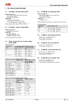
Page 20: ...i 0 mH Internal capacitance Ci 5 nF Ci 49 nF Maximum permissible external inductance Lo 5 mH Maximum permissible external capacitance Co 1 55 F Protection type Intrinsic Safety Ex ia IIC Part 2 Measur...

Page 21: ...upply circuit Max voltage Ui 9 V Short circuit current Ii 65 2 mA Max power Pi 101 W Internal inductance Li 0 mH Internal capacitance Ci 0 nF 6 1 4 Intrinsically Safe FM I S Class I Div 1 and Div 2 Gr...

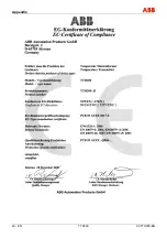
Page 22: ...ets the requirements of the following European directives EMC directive 89 336 EEC ATEX directive 94 9 EC Explosion Protection Identification for intended use in potentially explosive atmospheres acco...

Page 23: ...Appendix 22 EN TTH200 CI TTH200 EN...

Page 24: ...ithout notice Printed in the Fed Rep of Germany 03 2009 ABB 2009 3KXT231002R4401 CI TTH200 EN ABB Limited Salterbeck Trading Estate Workington Cumbria CA14 5DS UK Tel 44 0 1946 830 611 Fax 44 0 1946 8...

Reviews: