background image


— 

A B B   M E A S U RE M E N T   &  A NA L Y T IC S   |   OPE R A TI NG  I N ST R U CT I ON 

TTH200  

Head-mount temperature transmitter 

 
— 

ABB Limited 
Measurement & Analytics 

Howard Road, St. Neots 
Cambridgeshire, PE19 8EU 
UK 
Tel:  +44 (0)870 600 6122 
Fax:  +44 (0)1480 213 339 
Email: enquiries.mp.uk@gb.abb.com 
 

ABB Automation Products GmbH 
Measurement & Analytics 

Schillerstr. 72 
32425 Minden 
Germany 
Tel:   +49 571 830-0 
Fax:  +49 571 830-1806 
 

abb.com/temperature 

  
ABB Inc. 
Measurement & Analytics 

125 E. County Line Road 
Warminster, PA 18974 
USA 
Tel:  +1 215 674 6000 
Fax:  +1 215 674 7183 


Temperature transmitter for HART 
protocol. 
Suitable for all standard 
requirements 

Measurement made easy 


OI

/TTH2

00-E

N

 Re

v. B 

03.2

019


— 
TTH200 

Introduction 

The TTH200 with the 4 to 20 mA output and 
HART communications protocol has global 
approvals for explosion protection up to Zone 0. 
Safety-relevant applications up to SIL 3 
(redundant) are supported in accordance with 
IEC 61508.  
The TTH200 features a universal sensor input for 
resistance thermometer, thermocouples, 
resistance and voltage measurement. 


Additional Information 

Additional documentation on TTH200  is available for 
download free of charge at 
www.abb.com/temperature. 
Alternatively simply scan this code: 


— 
We reserve the right to make technical changes or modify the contents of this document 
without prior notice. With regard to purchase orders, the agreed particulars shall prevail.  
ABB does not accept any responsibility whatsoever for potential errors or possible lack of 
information in this document.  
 
We reserve all rights in this document and in the subject matter and illustrations contained 
therein. Any reproduction, disclosure to third parties or utilization of its contents – in whole 
or in parts – is forbidden without prior written consent of ABB. 
 
© ABB 2019 

3KXT231002R4201 


Summary of Contents for TTH200

Page 1: ...T communications protocol has global approvals for explosion protection up to Zone 0 Safety relevant applications up to SIL 3 redundant are supported in accordance with IEC 61508 The TTH200 features a universal sensor input for resistance thermometer thermocouples resistance and voltage measurement Additional Information Additional documentation on TTH200 is available for download free of charge a...

Page 2: ...e device 13 Storing the device 13 Ambient conditions 13 Returning devices 13 7 Installation 14 Installation options 14 Installation in the cover of the connection head 14 Installation on the measuring inset 14 Installation on the top hat rail 14 Installing removing the optional LCD indicator 15 Disassembling the LCD indicator 15 Installing the LCD indicator 15 Rotating the LCD indicator 15 8 Elect...

Page 3: ...the product may only be performed if expressly permitted by these instructions Information and symbols on the product must be observed These may not be removed and must be fully legible at all times The operating company must strictly observe the applicable national regulations relating to the installation function testing repair and maintenance of electrical products Warnings The warnings in thes...

Page 4: ...lterations releases the manufacturer from liability for any resulting damage This renders the manufacturer s warranty null and void Notes on data safety This product is designed to be connected to and to communicate information and data via a network interface It is operator s sole responsibility to provide and continuously ensure a secure connection between the product and your network or any oth...

Page 5: ...rking ATEX The device fulfills the requirements of Directive 2014 34 EU in case of corresponding purchase orders and is approved for use in Zone 2 Model TTH200 E2 Declaration of conformity II 3 G Ex nA IIC T1 T6 Gc IECEx intrinsic safety Approved for use in Zone 0 1 and 2 Model TTH200 H1 IECEx certificate of conformity IECEx PTB 09 0014X Ex ia IIC T6 T1 Ga Ex ia IIC Ga ib IIC T6 T1 Gb Ex ia IIIC D...

Page 6: ...tion Ex ia IIC part 1 Supply circuit Max voltage Ui 30 V Short circuit current Ii 130 mA Max power Pi 0 8 W Internal inductance Li 160 µH Internal capacitance Ci 0 57 nF From HW Rev 1 12 previously Li 0 5 mH From HW Rev 1 07 previously Ci 5 nF Intrinsic safety type of protection Ex ia IIC part 2 Thermocouples voltages Measurement circuit resistance thermometer resistances Measurement circuit therm...

Page 7: ...afe circuit needs to be grounded by means of a connection to the potential equalization it may only be grounded at one point Intrinsic safety installation check If transmitters are operated in an intrinsically safe circuit proof that the interconnection is intrinsically safe must be provided in accordance with IEC EN 60079 14 as well as IEC EN 60079 25 The supply isolators DCS inputs must feature ...

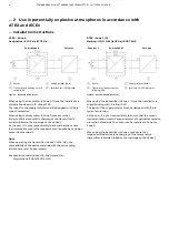
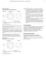
Page 8: ... explosion protection standards Note When operating the transmitter in Zone 0 EPL Ga the compatibility of the device materials with the surrounding atmosphere must be guaranteed Encapsulation material used for the transmitter Polyurethane PUR WEVO PU 417 ATEX Zone 1 0 Marking II 2 1 G Ex ia IIC Ga ib IIC T6 Gb Zone 0 or 1 Ex area Zone 1 Safe area A Sensor B Transmitter in housing with IP rating IP...

Page 9: ... Zone 2 observe the following The temperature transmitter must be installed in its own housing This housing must at least meet IP rating IP 54 in accordance with EN 60529 and other requirements for potentially explosive atmosphere e g a certified housing External measures must be made for the power supply circuit in order to prevent the rated voltage from being up scaled by more than 40 in the eve...

Page 10: ...Div 2 Group A B C D or I S Class I Zone 0 AEx ia IIC T Ui Vmax 9 V Ii Imax 65 2 mA Pi 101 mW Ci 0 4 μF Li 0 FM Non Incendive Control Drawing SAP_214 751 N I Class I Div 2 Group A B C D oder Ex nL IIC T Class I Zone 2 Ui Vmax 9 V Ii Imax 65 2 mA Pi 101 mW Ci 0 4 μF Li 0 CSA Intrinsically Safe Control Drawing SAP_214 749 I S Class I Div 1 and Div 2 Group A B C D or I S Zone 0 Ex ia IIC T Ui Vmax 9 V...

Page 11: ...quipment Supply isolator DCS input related equipment Ui Uo Ii Io Pi Po Li Lc cable Lo Ci Cc cable Co Field Ex area Control room safe area A Transmitter B Supply isolator DCS input with supply segment coupler Figure 6 Intrinsic safety installation check Installation in a potentially explosive atmosphere Transmitters can be installed in all kinds of industrial sectors Potentially explosive systems a...

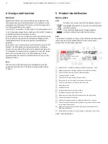
Page 12: ...ble with the TTH200 5 Product identification Name plate Note Products that are marked with the adjacent symbol may not be disposed of as unsorted municipal waste domestic waste They should be disposed of through separate collection of electric and electronic devices Note The ambient temperature range n provided on the name plate refers only to the transmitter itself and not to the sensor element u...

Page 13: ...aims for damages must be submitted to the shipper without delay and before installation Transporting the device Observe the following instructions Do not expose the device to humidity during transport Pack the device accordingly Pack the device so that it is protected against vibrations during transport for example by using air cushioned packing Storing the device Bear the following points in mind...

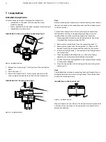
Page 14: ... toothed discs and the corresponding mounting screws are required these must be ordered as separate accessories Measuring inset installation set 2 fixing screws 2 springs 2 toothed discs order number 263750 1 Remove the ceramic block from the measuring inset 3 2 Remove the screws from the transmitter 2 Remove the sleeves from the screw holes and then remove the screws 3 Insert new fixing screws 1 ...

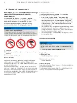
Page 15: ... it snaps into place 8 Electrical connections Safety instructions DANGER Improper installation and commissioning of the device carries a risk of explosion For use in potentially explosive atmospheres observe the information in Use in potentially explosive atmospheres in accordance with ATEX and IECEx on page 5 and Use in potentially explosive atmospheres in accordance with FM and CSA on page 10 Ob...

Page 16: ...n if temperature sensors are connected to the transmitter during installation but are not yet integrated into the system no connection to the supply isolator DCS Suited protective measures The following items should be observed to protect the transmitter from sensor side damage In the vicinity of the transmitter sensor and sensor connector cable in case of a connected sensor high energy overvoltag...

Page 17: ...er three wire circuit C Potentiometer two wire circuit D RTD four wire circuit E RTD three wire circuit F RTD two wire circuit G Voltage measurement H Thermocouple I Interface for type AS LCD indicator 1 to 4 Sensor connection of measuring inset 5 to 6 4 to 20 mA HART Figure 13 TTH200 connections Change from one to two columns ...

Page 18: ...500 Ω 0 6 to 10 kΩ Measuring range 0 to 5 Ω 5 3 to 10 kΩ Corrosion detection in accordance with NE 89 Three wire resistance measurement 50 Ω Four wire resistance measurement 50 Ω Sensor error signaling Resistance thermometer Sensor short circuit and sensor wire break Linear resistance measurement Sensor wire break Input thermocouples voltages Types B E J K N R S T in accordance with IEC 60584 U L ...

Page 19: ...ower supply Two wire technology polarity safe power supply lines signal lines Note Following calculations apply for standard applications This should be taken into consideration when working with a higher maximum current Input terminal voltage Non Ex application US 11 to 42 V DC Ex applications US 11 to 30 V DC Maximum permissible residual ripple for input terminal voltage During communication thi...

Page 20: ...signal line can be operated with without grounding When establishing a ground connection minus side make sure that only one side of the terminal is connected to the equipotential bonding 9 Commissioning General In case of corresponding order the transmitter is ready for operation after mounting and installation of the connections The parameters are set at the factory The connected lines must be ch...

Page 21: ...ccordance with NE 43 HART diagnosis Parameterization of the device Note The device does not have operating elements for parameterization on site Parameterization takes place via the HART interface Parameterization of the device takes place via standard HART tools These include ABB Handheld HART Communicator DHH805 TTX200 EDD ABB Asset Vision Basic TTX200 DTM ABB 800xA Control system TTX200 DTM ABB...

Page 22: ...mocouple type E IEC584 Thermocouple type J IEC584 Thermocouple type N IEC584 Thermocouple type R IEC584 Thermocouple type S IEC584 Thermocouple type T IEC584 Thermocouple type L DIN43710 Thermocouple type U DIN43710 Thermal voltage 125 to 125 mV Thermal voltage 125 to 1100 mV Resistance 0 to 500 Ω Resistance 0 to 5000 Ω Pt10 IEC751 Pt50 IEC751 Pt200 IEC751 Pt500 IEC751 Pt10 JIS1604 Pt50 JIS1604 Pt...

Page 23: ...a sensor or device error can be configured 20 to 23 6 mA Standard 22 mA Current output output upon error underrange Generates a low alarm signal in the event of a sensor or device error can be configured 3 5 to 4 mA Device Maintenance Poll address TAG HART TAG Defines the HART TAG name 8 characters alphanumeric Poll address TAG Address Multidrop Specifies the communication type Address 0 conforms ...

Page 24: ... factory The table below contains the relevant parameter values Menu Designation Parameter Factory setting Device Setup Write protection No Input Sensor Type Pt100 IEC60751 R Connection Three wire circuit Measured Range Begin 0 Measured Range End 100 Engineering Unit Degrees C Damping Off Process Alarm Fault signaling Overrange 22 mA Change from one to two columns ...

Page 25: ... Trim D A analog output adjustment is used to compensate for errors in the current input of the higher level system D A analog output adjustment for the transmitter can be used to modify the loop current so that the desired value is displayed in the higher level system Error compensation for the higher level system is possible at the lower range value with 4 mA and or 20 mA single point error corr...

Page 26: ... communication mode point to point operation When an address in the range 1 to 15 is used the device switches to the HART Multidrop mode This operating mode enables users to connect up to 15 devices to a power supply unit in parallel In multidrop mode an analog output signal that matches the process temperature is not available The output signal in multidrop mode is a constant 3 6 mA and is used e...

Page 27: ...sor Diagnosis for sensor elements and connection lines Installation Configuration Diagnosis for communication interface and parameterization configuration Operating conditions Diagnosis for ambient and process conditions Note For a detailed description of errors and troubleshooting instructions please see Diagnosis error messages on page 27 11 Diagnosis error messages The transmitter signals messa...

Page 28: ...ror sensor Check sensor connection Sensor F 35 Short circuit sensor Check sensor connection Sensor F 36 Wire break sensor Check sensor connection Sensor F 37 Range overshot sensor Check measuring limits Sensor F 38 Range undershot sensor Check measuring limits Installation Configuration I 41 Single point adjustment active sensor Status info not an error Installation Configuration I 42 Two point ad...

Page 29: ...ty instructions DANGER Explosion hazard Explosion hazard due to improper repair of the device Faulty devices may not be repaired by the operator The device may only be repaired by the ABB Service Department On site repair of the transmitter or exchange of electronic components is not permissible Returning devices Use the original packaging or a secure transport container of an appropriate type if ...

Page 30: ...G Electrical Equipment Act in Germany The product must be supplied to a specialist recycling company Do not use municipal waste collection points These may be used for privately used products only in accordance with WEEE Directive 2012 19 EU If there is no possibility to dispose of the old equipment properly our Service can take care of its pick up and disposal for a fee Trademarks HART is a regis...

Page 31: ...s Company Address Contact person Telephone Fax Email Device details Type Serial no Reason for the return description of the defect Was this device used in conjunction with substances which pose a threat or risk to health Yes No If yes which type of contamination please place an X next to the applicable items biological corrosive irritating combustible highly extremely combustible toxic explosive o...

Page 32: ...215 674 7183 OI TTH200 EN Rev B 03 2019 We reserve the right to make technical changes or modify the contents of this document without prior notice With regard to purchase orders the agreed particulars shall prevail ABB does not accept any responsibility whatsoever for potential errors or possible lack of information in this document We reserve all rights in this document and in the subject matter...

Reviews: