background image

62 

TTH300

 HEAD-MOUNT TEMPERATURE TRANSMITTER  |  OI/TTH300-EN REV. G 


… 10 Operation 


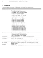
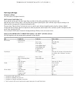
… Parameter description PROFIBUS PA® and FOUNDATION Fieldbus® 


Menu: Device Info 


Menu / parameter 

Description 

… / Device Info 

Device ID 

Displays device ID 

Serial Number 

Displays serial number 

Software Version 

Displays software version 

Hardware Version 

Displays hardware version 

TAG 

Displays measuring point tagging  

Description 

Displays a user-defined text 

Operation Time 

Displays operating hours 


Menu: Communication 


Menu / parameter 

Description 

… / Communication 

TAG 

Measuring point tagging  
•  16 characters 

Bus Address 

Address range during bus operation  
Value range: 0 to 125 

Ident Number 

PROFIBUS PA profile: selects ID numbers than can be used  
Manufacturer-specific: (IDENT__NUMBER_SELECT) only for PROFIBUS PA 

Ident Number Profile 

ID numbers used for profile with PROFIBUS PA 
•  1*AI (0x9700) 
•  2*AI (0x9701) 
•  3*AI (0x9702) 
•  4*AI (0x9703) 


Summary of Contents for TTH300 Series

Page 1: ...HART PROFIBUS PA and FOUNDATION Fieldbus communications protocols The transmitter has global approvals for explosion protection up to zone 0 The TTH300 implements various NAMUR recommendations including NE 89 and NE 107 Safety relevant applications up to SIL 3 redundant are supported in accordance with IEC 61508 Additional Information Additional documentation on TTH300 is available for download fr...

Page 2: ...ng the device 19 Storing the device 19 Ambient conditions 19 Returning devices 19 7 Installation 19 Ambient conditions 19 Ambient temperature 19 Transport Storage temperature 19 Climate class in accordance with DIN EN 60654 1 19 Max permissible humidity in accordance with IEC 60068 2 30 19 Vibration resistance in accordance with IEC 60068 2 6 19 Shock resistance in accordance with IEC 60068 2 27 1...

Page 3: ...g to the information level 38 Switching to the configuration level parameterization 38 Selecting and changing parameters 39 Entry from table 39 Parameter overview HART for devices to SW Rev 1 03 40 Parameter description HART for HART devices to SW Rev 1 03 42 Menu Device Setup 42 Menu Device Info 45 Menu Display 45 Menu Process Alarm 46 Menu Communication 46 Menu Calibrate 46 Menu Diagnosis 47 Act...

Page 4: ...ITTER OI TTH300 EN REV G 12 Maintenance 72 Safety instructions 72 Cleaning 72 13 Repair 72 Safety instructions 72 Returning devices 72 14 Recycling and disposal 73 15 Specification 73 16 Additional documents 73 17 Appendix 74 Return form 74 ...

Page 5: ...the product may only be performed if expressly permitted by these instructions Information and symbols on the product must be observed These may not be removed and must be fully legible at all times The operating company must strictly observe the applicable national regulations relating to the installation function testing repair and maintenance of electrical products Warnings The warnings in thes...

Page 6: ... unauthorized alterations releases the manufacturer from liability for any resulting damage This renders the manufacturer s warranty null and void Notes on data safety This product is designed to be connected to and to communicate information and data via a network interface It is operator s sole responsibility to provide and continuously ensure a secure connection between the product and your net...

Page 7: ...rements of Directive 2014 34 EU in case of corresponding purchase orders and is approved for use in Zone 2 Model TTH300 E2 Declaration of conformity II 3 G Ex nA IIC T6 T1 Gc II 3 G Ex ec IIC T6 T1 Gc IECEx intrinsic safety Approved for use in Zone 0 1 and 2 Model TTH300 H1H To HW Rev 1 07 IECEx certificate of conformity From HW Rev 02 00 00 IECEx certificate of conformity IECEx PTB 09 0014X IECEx...

Page 8: ... Short circuit current Ii 130 mA Ii 183 mA2 Ii 250 mA Max power Pi 0 8 W Pi 2 56 W2 Pi 1 2 W Internal inductance Li 160 μH3 Li 10 μH Li 10 μH Internal capacitance Ci 0 57 nF4 Ci 5 nF Ci 5 nF 1 FISCO according to 60079 27 2 II B FISCO Ii 380 mA Pi 5 32 W 3 For HART variant only From Hardware Rev 02 00 00 previously 0 5 mH 4 For HART variant only From hardware revision 1 07 previously 5 nF Intrinsic...

Page 9: ... negligible Installation instructions ATEX IECEx The installation commissioning maintenance and repair of devices in potentially explosive atmospheres must only be carried out by appropriately trained personnel Works may be carried out only by persons whose training has included instructions on different types of protection and installation techniques concerned rules and regulations as well as gen...

Page 10: ... with supply segment coupler Figure 1 Intrinsic safety installation check Installation in a potentially explosive atmosphere Transmitters can be installed in all kinds of industrial sectors Potentially explosive systems are divided into zones meaning that a wide range of different instruments are also required For this pay attention to the country specific guidelines and certificates Note Ex relev...

Page 11: ...must ensure that impermissible electrostatic charging of the temperature transmitter is prevented observe the warnings on the device ATEX Zone 1 20 Marking II 2 G 1D Ex ia IIIC Da ib IIC T6 T1 Gb Zone 20 or 21 Ex area Zone 1 Safe area A Sensor B Transmitter in housing with IP rating IP 20 C Supply isolator Ex ib D Interface for LCD indicator Figure 4 Hookup in ATEX Zone 1 20 When using the transmi...

Page 12: ...the power supply circuit in order to prevent the rated voltage from being up scaled by more than 40 in the event of transient disturbances The electrical connections must only be opened or closed when there is no hazardous atmosphere When using the transmitter in Zone 2 make sure that impermissible electrostatic charging of the temperature transmitter is prevented observe the warnings on the devic...

Page 13: ...m HW Rev 02 00 00 Control Drawing See attached information Model TTH300 R1P Control Drawing TTH300 R1P IS Model TTH300 R1F Control Drawing TTH300 R1F IS Class I Div 1 2 Groups A B C D Class I Zone 0 Ex ia IIC T6 CSA Non Incendive Model TTH300 R2H To HW Rev 1 07 Control Drawing SAP_214824 Non Incendive SAP_214896 Non Incendive From HW Rev 02 00 00 Control Drawing See attached information Model TTH3...

Page 14: ...y of the device materials with the surrounding atmosphere must be guaranteed Encapsulation material used for the transmitter Polyurethane PUR WEVO PU 417 Proof of intrinsic safety is said to have been provided if the following conditions are fulfilled when a comparison is carried out in relation to the limit values of the equipment Transmitter intrinsically safe equipment Supply isolator DCS input...

Page 15: ... pin flat ribbon cable with a plug connector The LCD display can only be operated when connected to transmitters that have an LCD display interface Input functionality Sensor Redundancy To enhance system availability the TTH300 has two sensor inputs The second sensor input can be used redundantly for both resistance thermometers 2 x three wire circuit or 2 x two wire circuit and thermocouples or a...

Page 16: ...ted output of set alarm current Redundancy Safety Redundancy S1 not available Failure Redundancy S2 not available Failure Sensor drift detected Failure Increased accuracy through averaging Output signal follows the arithmetic mean value of sensor 1 and sensor 2 Sensor 1 or sensor 2 defective output of set alarm current Mean value not relevant Redundancy S1 not available Failure Redundancy S2 not a...

Page 17: ...ocouple is used for drift monitoring of a resistance thermometer the resistance thermometer must be connected to channel 1 and the thermocouple to channel 2 see Electrical connections on page 21 The measured value of channel 1 resistance thermometer is mapped as a process variable at the transmitter output Sensor drift monitoring with redundancy operation devices with HART from SW Rev 3 00 If a th...

Page 18: ...measuring range of the transmitter l Measuring point tag TAG in accordance with order optional m Set sensor type and circuit type l m Transmitter FOUNDATION Fieldbus or PROFIBUS PA l Measuring point tag TAG in accordance with order optional m DEVICE_ID or Ident_Number n Ambient temperature range on additional plate for Ex versions o Transmitter specification supply voltage range output current ran...

Page 19: ...device correspond to the ambient conditions for operation of the device Adhere to the device data sheet Returning devices For the return of devices follow the instructions in Repair on page 72 7 Installation DANGER Improper installation and commissioning of the device carries a risk of explosion For use in potentially explosive atmospheres observe the information in Use in potentially explosive at...

Page 20: ...the transmitter 2 Remove the sleeves from the screw holes and then remove the screws 3 Insert new fixing screws 1 from above in the fixing holes of the transmitter 4 Place the cambered toothed discs 4 with curve facing upward on the downward protruding screw thread 5 Connect the power supply cable to the transmitter according to connection diagram 6 Place the transmitter in the housing on the meas...

Page 21: ... it snaps into place 8 Electrical connections Safety instructions DANGER Improper installation and commissioning of the device carries a risk of explosion For use in potentially explosive atmospheres observe the information in Use in potentially explosive atmospheres in accordance with ATEX and IECEx on page 7 and Use in potentially explosive atmospheres in accordance with FM and CSA on page 13 Ob...

Page 22: ... can already happen if temperature sensors are connected to the transmitter during installation but are not yet integrated into the system no connection to the supply isolator DCS Suited protective measures The following items should be observed to protect the transmitter from sensor side damage In the vicinity of the transmitter sensor and sensor connector cable in case of a connected sensor high...

Page 23: ...e wire circuit E 2 RTD two wire circuit F RTD four wire circuit G RTD three wire circuit H RTD two wire circuit I Sensor 1 J Sensor 2 K Interface for LCD indicators and service 1 6 Sensor connection of measuring inset 7 8 4 to 20 mA HART PROFIBUS PA FOUNDATION Fieldbus Sensor backup sensor redundancy sensor drift monitoring mean measurement or differential measurement Figure 15 Terminal assignment...

Page 24: ...circuit and 1 x thermocouple F 1 RTD three wire circuit and 1 x thermocouple G 1 RTD two wire circuit and 1 x thermocouple H Sensor 1 I Sensor 2 J Interface for LCD indicators and service 1 6 Sensor connection of measuring inset 7 8 4 to 20 mA HART PROFIBUS PA FOUNDATION Fieldbus Sensor backup sensor redundancy sensor drift monitoring mean measurement or differential measurement Figure 16 Terminal...

Page 25: ...rt circuit and sensor wire break Linear resistance measurement Sensor wire break Input thermocouples voltages Types B E J K N R S T in accordance with IEC 60584 U L in accordance with DIN 43710 C in accordance with IEC 60584 ASTM E988 D in accordance with ASTM E988 Voltages 125 to 125 mV 125 to 1100 mV Connection lead Maximum sensor line resistance per line 1 5 kΩ total 3 kΩ Detection of sensor wi...

Page 26: ...mA From SW Rev 3 00 Note The default factory setting for the error current signal is low alarm 3 5 mA in accordance with NAMUR recommendations NE 93 NE 107 and NE 131 Overrange high alarm 22 mA 20 0 to 23 6 mA Underrange low alarm 3 5 mA 3 5 to 4 0 mA Output PROFIBUS PA Note The PROFIBUS PA protocol is an unsecured protocol as such the intended application should be assessed to ensure that these p...

Page 27: ...1 Transducer Block 3 Discrete Input 2 extended diagnosis 2 Transducer Block 3 PID PID controller LAS Link Active Scheduler link master functionality For the block description block index execution times and block class refer to the interface description Sensor 1 Sensor 2 or difference or mean Power supply Two wire technology polarity safe power supply lines signal lines Note Following calculations...

Page 28: ...ity Adding resistance R250 increases the minimum supply voltage U2min U1min U2min 22 mA R R250 For HART functionality use supply isolators or DCS input cards with a HART mark If this is not possible a resistance of 250 Ω 1100 Ω must be added to the interconnection The signal line can be operated with without grounding When establishing a ground connection minus side make sure that only one side of...

Page 29: ...both wires of the signal line in accordance with the HART FSK Physical Layer specification The HART modem is connected at the signal line of the current output via which power is also supplied via the power supply unit The device is listed with the FieldComm Group 1 Transmitter 2 Handheld terminal 3 HART modem 4 PC with Asset Management Tool 5 Grounding optional 6 Power supply unit process interfa...

Page 30: ...ion changes The information can be output via tools Event monitor for logging critical events Configuration monitor for configuration changes See the interface description HART COM TTX300 HART for details PROFIBUS Communication Note The PROFIBUS PA protocol is an unsecured protocol as such the intended application should be assessed to ensure that these protocols are suitable before implementation...

Page 31: ...figuration of the transmitter via HART PROFIBUS PA and FOUNDATION Fieldbus H1 are described in the separate documentation Interface Description for the relevant protocol COM TTX300 The following configuration types are available for the transmitter With DTM Configuration can be performed within an FDT frame application that is approved for use with the DTM With EDD Configuration can be performed w...

Page 32: ...not for HART devices from HW Rev 2 00 The transmitter has two DIP switches that can be accessed via a hinged cover Switch 1 activates the hardware write protection Switch 2 supports the FOUNDATION Fieldbus requirement for a hardware enable for simulation in accordance with ITK For transmitters that support HART 7 switch 2 allows the desired HART version to be set HART 5 or HART 7 DIP switch Functi...

Page 33: ...CD indicator example You can use the or operating buttons to browse through the menu or select a number or character within a parameter value Different functions can be assigned to the and operating buttons The function 5 that is currently assigned to them is shown on the LCD display Control button functions Meaning Exit Exit menu Back Go back one submenu Cancel Cancel a parameter entry Next Selec...

Page 34: ... Signal View Display Process Alarm Communication Calibrate Diagnosis Device Info Service Process display The process display shows the current process values Operator menu On the information level the operator menu can be used to display diagnostic information and choose which operator pages to display Configuration level The configuration level contains all the parameters required for device comm...

Page 35: ...ll Service Signal View Display Calibrate Process display The process display shows the current process values Information level The information level contains the parameters and information that are relevant for the operator The device configuration cannot be changed on this level Configuration level The configuration level contains all the parameters required for device commissioning and configur...

Page 36: ...l The device is protected against changes in the parametrization Error messages in the HART LCD display In the event of an error different information appears depending on the revision To SW Rev 1 03 A symbol or letter Device Status and a number DIAG NO As of SW Rev 3 00 Corresponding device status symbol and associated diagnostics group Process display To SW Rev 1 03 Application F72 Process displ...

Page 37: ...a message consisting of a symbol and text appears at the bottom of the process screen e g electronics The text displayed provides information about the area in which the error has occurred Process display Elektronik The error messages are divided into four groups in accordance with the NAMUR classification scheme The group assignment can only be changed using a DTM or EDD Symbol Description Error ...

Page 38: ...messages in the HART LCD display on page 36 und Error messages in the LCD display PROFIBUS PA and FOUNDATION Fieldbus on page 37 Operator Page 1 Selection of operator page to be displayed Operator Page 2 Autoscroll When Multiplex mode is activated automatic switching of the operator pages is initiated on the process screen Signal View Selects the Signal View submenu in which all dynamic measured v...

Page 39: ...ting The decimal place that is currently selected is highlighted Parameter name 12 3456 unit Next OK 3 Use to select the decimal place to change 4 Use to set the desired value 5 Use to select the next decimal place 6 If necessary select and set additional decimal places in accordance with steps 3 to 4 7 Use to confirm your setting This concludes the procedure for changing a parameter value Alphanu...

Page 40: ...ion has changed In addition for devices from SW Rev 3 00 additional information event and configuration monitor see interface description HART COM TTX300 HART and detailed diagnostics can be displayed and configured in tools drivers such as FIM and DTM Device Setup 1 Write protection Input Sensor 1 Sensor Type R Connection 2 wire Resistance Thermocouple RJ ext Thermocouple RJ Input Sensor 2 Input ...

Page 41: ...E TRANSMITTER OI TTH300 EN REV G 41 Calibrate 6 Measured range Apply Lower Range Apply Upper Range Analog Out Trim 4 mA Trim 20 mA Diagnosis 7 Looptest Device status Temp of Electronics Sensor 1 process data Sensor 2 process data ...

Page 42: ...output signal damping value Value range 0 to 100 s Factory reset Resets configuration data adjustment data trim high low and DAC adjustment values to factory settings Yes OK Device Setup Input Sensor 1 Device Setup Input Sensor 2 Sensor Type Selects sensor type Pt100 IEC751 Resistance thermometer Pt100 IEC751 Pt1000 IEC751 Resistance thermometer Pt1000 IEC751 TC type K IEC584 Thermocouple type K I...

Page 43: ...Pt50 MIL24388 Pt100 MIL24388 Resistance thermometer Pt100 MIL24388 Pt200 MIL24388 Resistance thermometer Pt200 MIL24388 Pt1000 MIL24388 Resistance thermometer Pt1000 MIL24388 Ni50 DIN43760 Resistance thermometer Ni50 DIN43716 Ni100 DIN43760 Resistance thermometer Ni100 DIN43716 Ni120 DIN43760 Resistance thermometer Ni120 DIN43716 Ni1000 DIN43760 Resistance thermometer Ni1000 DIN43716 Cu10 a 4270 R...

Page 44: ... Thermocouple RJ Internal Use of internal reference junction of the transmitter when using thermal compensating cable External fixed Use of external fixed reference junction of the transmitter when constant thermostat temperature is used can be set with ext Thermocouple RJ Without no Thermocouple RJ Sensor 1 Use of sensor 1 as reference junction for sensor 2 ext Thermocouple RJ Relevant for extern...

Page 45: ...he process variable shown in the process display Process Variable Calculated process variable PV Sensor 1 Measured value from Sensor 1 Sensor 2 Measured value from Sensor 2 Electr Meas S1 Measured value from Sensor 1 in Ω or mV Electr Meas S2 Measured value from Sensor 2 in Ω or mV Temp Electronics Temperature of the transmitter Output Current Output current of 4 to 20 mA signal Output Output valu...

Page 46: ...ltidrop mode HART Burstmode Status on off Switches burst operating mode on or off Command 1 2 3 33 sets the HART command to be sent cyclically HART Resp Preambles Number of preambles to be used for sending Value range 5 to 20 Menu Calibrate Menu parameter Description Calibrate Measured range Select the Measured range submenu Analog Out Select the Analog Out submenu Calibrate Measured range Apply L...

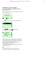
Page 47: ...elect the sub item Write protection Displays the current write protection setting 2 Use the Edit button to edit the current write protection configuration 3 Use the or buttons to select at least one alphanumeric character up to 4 may be selected and confirm via the button Note Spaces and the number combination 0110 must not be entered 4 Write protection YES is displayed Click the button 3 times to...

Page 48: ...sed from SW Rev 3 00 Additional device and diagnostic information is provided The setting and canceling of write protection has changed In addition for devices from SW Rev 3 00 additional information event and configuration monitor see interface description HART COM TTX300 HART and detailed diagnostics can be displayed and configured in tools drivers such as FIM and DTM Easy Setup 1 Language HART ...

Page 49: ... output assignment Redundancy Configuration PV Measured range PV Unit PV Lower Range Value PV Upper Range Value PV Damping Display 3 Language Contrast Mode Operator Page 1 Line 1 View Line 2 View Bargraph View Test Process Alarm 4 Fault signaling Communication 5 HART TAG HART LONG TAG Address Multidrop Address HART 7 Current Loop Mode HART Burstmode Status Command HART Resp Preambles Find Device H...

Page 50: ...A Diagnosis 7 Looptest Device status SIL Check Not passed chk Tool Passed Temp of Electronics MIN Value MAX Value Processvalue Sensor 1 MIN Value MAX Value Reset Processvalue Sensor 2 MIN Value MAX Value Reset Device Info 8 Device Type Serial Number Device SerialNo acc Order Software Version Hardware Version HART TAG HART LONG TAG HART Descriptor HART Message Operation Time Service 9 Factory reset...

Page 51: ...ermometer Pt200 IEC751 Pt500 IEC751 Resistance thermometer Pt500 IEC751 Pt1000 IEC751 Resistance thermometer Pt1000 IEC751 Pt50 JIS1604 Resistance thermometer Pt50 JIS1604 Pt100 JIS1604 Resistance thermometer Pt100 JIS1604 Pt50 IMIL24388 Resistance thermometer Pt50 MIL24388 Pt100 MIL24388 Resistance thermometer Pt100 MIL24388 Pt200 MIL24388 Resistance thermometer Pt200 MIL24388 Pt1000 MIL24388 Res...

Page 52: ...ic curve 1 Fixpoint table 2 Customer specific characteristic curve 2 Fixpoint table 3 Customer specific characteristic curve 3 Fixpoint table 4 Customer specific characteristic curve 4 Fixpoint table 5 Customer specific characteristic curve 5 off Sensor channel deactivated sensor 2 only R Connection S1 Sensor connection type relevant for all Pt Ni Cu resistance thermometers Two wire sensor connect...

Page 53: ...temperature of the transmitter when constant thermostat temperature is used can be set with external cold junction temperature 2 None no thermocouple cold junction compensation CJC Sensor 1 temperature Use of sensor 1 as cold junction temperature for sensor 2 Ext CJC Temperature 2 Relevant for external cold junction compensation specification of constant external cold junction temperature Value ra...

Page 54: ...see table of sensortypes Easy Setup sensortype S1 R Connection Sensor connection type relevant for all Pt Ni Cu resistance thermometers two wire Sensor connection type in two wire technology three wire Sensor connection type in three wire technology four wire Sensor connection type in four wire technology 2 wire Resistance Sensor line resistance relevant for all Pt Ni Cu resistance thermometers wi...

Page 55: ... 1 sensor 2 Difference S2 S1 Calculate difference sensor 2 sensor 1 Average S1 S2 Calculate average of sensor 1 and sensor 2 Redundancy S1 S2 Redundancy of sensor 1 and sensor 2 Electr meas S1 Measured value from sensor 1 in Ω or mV Electr meas S2 Measured value from sensor 2 in Ω or mV Electronics temp Temperature of the transmitter Output current Output current of 4 to 20 mA signal Output Output...

Page 56: ...e HART Burstmode submenu HART Resp Preambles Number of preambles to be used for sending Value range 5 to 20 Find Device This option helps with finding a device The HART master sends HART command 73 to search for the device Device answeres with HART initialize Command 0 long address if found Options Disabled no reaction HART command 0 One Time Once time reaction HART command 0 Continous Always reac...

Page 57: ...Description Diagnosis Looptest Simulates the current output signal Value range 3 500 to 23 600 mA 0 000 mA ends looptest Device status Diagnostic notice maintenance required failure etc SIL Check Select the SIL Check submenu Not passed Use tool for a detailed check of the current device configuration Passed SIL Configuration Check successful The device configuration is valid for SIL Safety applica...

Page 58: ... LONG TAG Display the HART long tag HART Descriptor Displays the HART Descriptor HART Message Display the HART message Operation Time Displays device the operation time Menu Service Menu parameter Description Service Factory reset Device restarts with factory settings applied Reset to Order Device restarts with settings according to the customer order Device Reset Device restarts without configura...

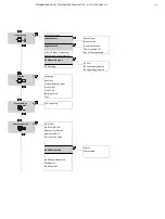
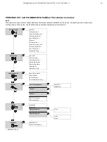
Page 59: ...re correction 1 Thermocouple RJ 1 Ext CJC Temp 1 Sensor 2 R Connection 2 two wire correction 2 Thermocouple RJ 2 Ext CJC Temp 2 Measured Type Device Info 2 Device ID Serial Number Software Version Hardware Version Device Tag Name Description Operation Time Communication 3 Device Tag Name Bus Address Ident Number Ident Number Profile1 Service 4 Device temperature MIN Value MAX Value Sensor 1 Sensor...

Page 60: ... T IEC584 TC type L DIN43710 Thermocouple type L DIN43710 TC type U DIN43710 Thermocouple type U DIN43710 125 125 mV Linear voltage measurement 125 to 125 mV 125 1100 mV Linear voltage measurement 125 to 1100 mV 0 500 Ω Linear resistance measurement 0 to 500 Ω 0 5000 Ω Linear resistance measurement 0 to 5000 Ω Pt10 IEC751 Resistance thermometer Pt10 IEC751 Pt50 IEC751 Resistance thermometer Pt50 I...

Page 61: ...Dusen coefficient set 4 Cal Van Dusen 5 Callendar Van Dusen coefficient set 5 off Sensor channel deactivated sensor 2 only only for communication protocol PROFIBUS PA Device Setup R Connection 1 R Connection 2 Sensor connection type relevant for all Pt Ni Cu resistance thermometers two wire Sensor connection type in two wire technology three wire Sensor connection type in three wire technology fou...

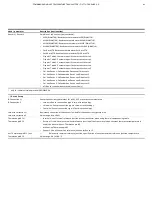
Page 62: ...sion TAG Displays measuring point tagging Description Displays a user defined text Operation Time Displays operating hours Menu Communication Menu parameter Description Communication TAG Measuring point tagging 16 characters Bus Address Address range during bus operation Value range 0 to 125 Ident Number PROFIBUS PA profile selects ID numbers than can be used Manufacturer specific IDENT__NUMBER_SE...

Page 63: ...ing hours at 20 C to 0 C 0 to 20 C operating hours at 0 to 20 C 20 to 40 C operating hours at 20 to 40 C 40 to 60 C operating hours at 40 to 60 C 60 to 85 C operating hours at 60 to 85 C 85 C operating hours at 85 C Communication Displays the communication quality Excellent Very good Good Poor None Service Menu Device temperature min Drag indicator minimum device temperature max Drag indicator max...

Page 64: ...he Operator Page 2 submenu Display Operator Page 1 Line 1 Selects the value displayed Calculated value Sensor 1 Sensor 2 Device temperature AO Block Display Operator Page 2 Line 1 Selects the value displayed in Line 1 Calculated value Sensor 1 Sensor 2 Device temperature AO Block Line 2 Selects the value displayed in Line 2 Calculated value Sensor 1 Sensor 2 Device temperature AO Block Menu Calibr...

Page 65: ...ces with PROFIBUS PA FOUNDATION Fieldbus and HART all SW revisions The following table with the corresponding parameter values applies Menu Designation Parameter Factory setting Device Setup Write protection No Input Sensor 1 Sensor Type Pt100 IEC60751 R Connection Three wire Measured Range Begin1 0 Measured Range End1 100 Engeneering Unit Degrees C Damping Off Process Alarm Fault signaling1 To SW...

Page 66: ...sensor type e g Pt100 to thermocouple type K the value is reset automatically Min reading for sensors 1 2 Smallest measured value on Sensor 1 or 2 When changing the sensor type the value is reset automatically Reset The drag indicators for the sensor readings are all reset to the current measured value in each case Operating hours statistics Value Description Operation Time Total hours since commi...

Page 67: ...osis 3 Confirm the selection with Electronics F123 321 Brief description Information Back Exit The error message is shown on the display according to priority The first line shows the area in which the error has occurred The second line shows the unique error number It is made up of the priority Fxxx and the error position xxx The next lines show a brief description of the error and information on...

Page 68: ...ics F 14 Sensor input defective ADC error Replace the device Installation Configuration C 32 Simulation mode Exit simulation mode Sensor F 34 Measuring error sensor 1 Check sensor connection Sensor F 35 Short circuit sensor 1 Check sensor connection Sensor F 36 Wire break sensor 1 Check sensor connection Sensor F 37 Range exceeded sensor 1 Check measuring limits Sensor F 38 Range undershot sensor ...

Page 69: ...k configuration connections reset to factory settings Installation Configuration I 74 Analog output adjustment active Terminate compensation Installation Configuration C 75 Analog output in simulation Terminate simulation Operating conditions S 76 Values overshot Check parameters A Sensor limits overshot B Span is too small Operating conditions S 77 Limit HIGH HIGH Upper limit value alarm Operatin...

Page 70: ...Operation Diagnostics is simulated Check function Terminate come out of simulation Operation Analog output fixed simulated Check function Terminate come out of simulation Operation Application warning Check function Load valid parameter restart reset check S1 S2 Electronics Electronics temp measurement failure Error Restart RESET or replace transmitter Electronics Electronics temp out of spec Out ...

Page 71: ...ions S2 measuring range overflow Outside of the specification Adapt S2 measuring range to suit measuring task Operating conditions S2 measuring range underflow Outside of the specification Adapt S2 measuring range to suit measuring task Operating conditions Device temperature out of spec Outside of the specification Check environment reposition measuring point if required Electronics Device error ...

Page 72: ...ety instructions DANGER Explosion hazard Explosion hazard due to improper repair of the device Faulty devices may not be repaired by the operator The device may only be repaired by the ABB Service Department On site repair of the transmitter or exchange of electronic components is not permissible Returning devices Use the original packaging or a secure transport container of an appropriate type if...

Page 73: ... specialist recycling company Do not use municipal waste collection points These may be used for privately used products only in accordance with WEEE Directive 2012 19 EU If there is no possibility to dispose of the old equipment properly our Service can take care of its pick up and disposal for a fee 15 Specification Note The device data sheet is available in the ABB download area at www abb com ...

Page 74: ...s Company Address Contact person Telephone Fax Email Device details Type Serial no Reason for the return description of the defect Was this device used in conjunction with substances which pose a threat or risk to health Yes No If yes which type of contamination please place an X next to the applicable items biological corrosive irritating combustible highly extremely combustible toxic explosive o...

Page 75: ...TTH300 HEAD MOUNT TEMPERATURE TRANSMITTER OI TTH300 EN REV G 75 Notes ...

Page 76: ... notice With regard to purchase orders the agreed particulars shall prevail ABB does not accept any responsibility whatsoever for potential errors or possible lack of information in this document We reserve all rights in this document and in the subject matter and illustrations contained therein Any reproduction disclosure to third parties or utilization of its contents in whole or in parts is for...

Reviews: