background image

On-load tap-changers, type UBB

Installation and commissioning guide

1ZSE 5492-118 en, Rev. 4

Summary of Contents for UBB Series

Page 1: ...On load tap changers type UBB Installation and commissioning guide 1ZSE 5492 118 en Rev 4 ...

Page 2: ...This document must not be copied without our written permission and the contents thereof must not be imparted to a third party nor be used for any unauthorized purpose Contravention will be prosecuted ...

Page 3: ...es additional information to assist in carrying out the work de scribed Safety precautions WARNING Unused transformer oil is slightly harmful Fumes from unused warm oil may irritate the respiratory organs and the eyes After long and repeated contact with transformer oil skin becomes very dry Used on load tap changer oil from diverter switch housings and selector switch housings contains harmful su...

Page 4: ...xiliary power must be switched off N B The motor contactors and heating element may be energized from separate sources During drying of the transformer CAUTION During drying with hot air and vacuum the maximum permitted pressure difference for the on load tap changer is 100 kPa at a maximum permitted temperature of 135 C 275 F During drying by the vapour phase process the cover of the selector swi...

Page 5: ...absorption in the oil from the gas cushion in the on load tap changer if the on load tap changer is not operated Restore the gas cushion and the oil level according to section 7 5 During service WARNING Small amounts of explosive gases will always come out from the breathing devices dehydrating breather or one way breather Make sure that no open fire hot surfaces or sparks occur in the immediate s...

Page 6: ......

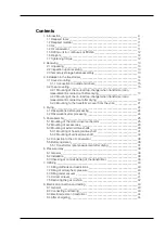
Page 7: ...______________24 4 2 Observations after processing_____________________________________24 5 Final assembly______________________________________________________25 5 1 Mounting of the motor drive mechanism_ ___________________________25 5 2 Mounting of accessories__________________________________________28 5 3 Mounting of external drive shafts___________________________________29 5 3 1 Mounting of...

Page 8: ...___________________________46 10 2 Oil filling_______________________________________________________46 10 3 Electrical connection and testing__________________________________46 10 3 1 Motor protection_ ___________________________________________46 10 3 2 Disc brake_________________________________________________47 10 3 3 Counter___________________________________________________47 10 3 4 Positi...

Page 9: ...ying and without having the transformer cover mounted The transformer cover is then lowered onto the tank and the on load tap changer is lifted and bolted to the cover Please use the appropriate instruction for cover mounting or yoke mounting The motor drive mechanism and bevel gear are fitted to the transformer tank and the drive shafts are fitted to complete the assembly of motor drive mechanism...

Page 10: ...ctor switch Cylinder Flange Bevel gear Oil valve Selector switch shaft Fig 2 General arrangement of on load tap changer type UB Transition resistor Current collector terminal Shielding rings Indicator window Air release valve to on load tap changer Connection to oil conservator Pressure relay Air release valve to transformer tank Top cover 1 Introduction ...

Page 11: ...ling in this guide 1 4 Oil conservator The on load tap changer has to be connected to an oil conservator ABB recommends the use of a separate conservator for the on load tap changer with both oil and air side sepa rated from the main conservator of the transformer The volume of the conservator should be such that there is oil left in the conservator even at the lowest oil temperature expected and ...

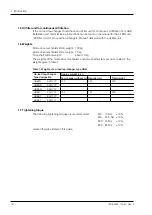
Page 12: ...kg Motor drive mechanism BUL weight 75 kg Drive shaft system weight about 10 kg The weights of the motor drive mechanism and drive shaft system are not included in the weights given in table 1 Table 1 Weights of on load tap changer type UBB On load tap changer Type designation Approx weight in kg Tap changer without oil Required oil Total weight UBBLN XXX YYY 140 100 240 UBBRN XXX YYY UBBDN XXX YY...

Page 13: ...tos are taken of the damaged details Mark the photos with ABB s reference number and the serial number of the on load tap changer and send them to ABB for comments 3 Check that the parts delivered type designations and the serial number agree with the delivery documents e g the packing list or ABB s ordering acknowledgement The se rial number is stamped on the rating plate and on the on load tap c...

Page 14: ...ot included in the on load tap changer delivery 2 Check that the on load tap changer flange is positioned in the right way in rotational relation to the transformer cover 3 Lower carefully without damaging the terminals the whole on load tap changer through the hole in the transformer cover If the on load tap changer is equipped with tie in resistors mounted on the outside terminals they have to b...

Page 15: ...way that there is no risk for them to come loose Furthermore the conductors must not cause mechanical stresses on the out side terminals Make an expansion bend on every conductor See Fig 5 Wrong Right CAUTION It is recommended that the distance between the cylinder and any conductor is at least 50 mm The transformer designer is responsible for providing sufficient insulating distances in the oil N...

Page 16: ...on the fork they should be insulated with bushings to prevent circulation currents in the fork when the transformer is in operation Mounting of the on load tap changer to the yoke fork can be made according to two alter natives depending on when the testing of the transformation ratio shall be performed Transformer ratio measurement before drying see section 3 2 1 Transformer ratio measurement aft...

Page 17: ...end positions on the single phase diagram and watch the position indicator in the bevel gear in order to avoid overrunning of the end position Watch the voltmeter during the on load tap changer operations No fast voltage drops may occur during operation If such drops occur the on load tap changer is not correctly con nected to the winding 6 After the measurement the position of the on load tap cha...

Page 18: ...118 en Rev 4 fm_00209 FM_00203 3 Installation in the transformer Fig 8a Fig 8b Fig 8c Approx 15 mm Sealing for suction pipe max 90o max 90o O ring for upper flange O ring for upper flange Fig 7 O ring for top cover ...

Page 19: ...ge the cover the O rings and the sealing for the suction pipe see Fig 8 and store them temporarily on a dustfree place NOTE The gear mechanism on the gear base plate needs not and shall not be re moved because it is fixed in the lower part 3 When lifting the on load tap changer onto the yoke fork it is recommended that lifting eyes M12 are mounted in the lower flange NOTE Check that the on load ta...

Page 20: ...the lifting eyes when the on load tap changer is in right position on the yoke fork 5 The on load tap changer and the transformer is now ready for drying Follow the in structions in chapter 4 3 Installation in the transformer Approx 15 mm Fig 10 ...

Page 21: ... Nut M12 16x Screw M8 12x Washer Upper flange 13 Guiding pin 10 5 15 Stud M12 16x Yoke fork Lower flange Cylinder O ring Gasket Not included in the delivery Lifting bar Gear mechanism 1 Place the O ring in its groove in the lower flange 2 Place the gasket around the opening of the transformer cover This gasket is not in cluded in the on load tap changer delivery Fig 11 Mounting onto the transforme...

Page 22: ... lifting bar and mount a washer and a screw in each of the free holes 10 An alternative method if the lifting bar is not available is to use 4 studbolts M8x70 for lifting the cylinder Place the studs at opposite directions through the clearance holes in the upper flange and threaded into the lower flange Mount washers and nuts on the studs Then lift the cylinder by tightening of the nuts Check whe...

Page 23: ...1ZSE 5492 118 en Rev 4 A A fm_00012 3 Installation in the transformer Fig 12 Cover Bevel gear Top cover Driving pin Hose clip Protective tube Screw M6 Coupling half A Guiding pin Driving disc View A A Key ...

Page 24: ... shall be removed See section 3 2 2 point 1 To open the bottom valve proceed as follows 2 Use the delivered bottom valve key to engage the internal hexagon hole of the bottom valve Open the valve by turning anticlockwise max 4 turns 3 When drying in a vacuum pan with the hot air process the top cover of the on load tap changer the O ring and sealing of the suction pipe shall be removed See section...

Page 25: ...transformer should be leveled within 1 mm If adjustment is needed shims should be used 2 Install the bevel gear on the edge of the transformer cover 3 Check that the position indicator in the motor drive mechanism shows the same posi tion as the indicator inside the top cover of the on load tap changer WARNING Do not energize the transformer before the on load tap changer and motor drive mechanism...

Page 26: ...ev 4 9 9 9 9 8 7 LOWER POSITION RAISE 9 8 7 6 5 4 10 11 12 13 14 9 fm_00240 fm_00235 5 Final assembly Fig 13 Position alignment for type BUE Indicator window Adjustment nuts Red mark Position indicator Brake disc Brake pads ...

Page 27: ...3 14 15 16 17 18 19 fm_00241 fm_00235 5 Final assembly Fig 14 Position alignment for type BUL Indicator window Cam disc Brake disc Adjusting screw Contra nut Brake arm Roller on brake arm in the notch of the cam disc Position indication White indicator flag ...

Page 28: ...on of the conservator and the oil filter unit if any The flanges A are equal and their accessories can be changed between them We recommend that the air release valve to the transformer see Fig 2 is replaced by a pipe to the gas operated relay in order to get a signal from the relay as quick as possible in case of gas production in the transformer CAUTION The pressure relay is a calibrated monitor...

Page 29: ...e cleaned and greased for cor rect function and to avoid corrosion Apply a thin layer of grease GULF 718EP Synthetic grease or Mobilgrease 28 or SHELL Aero Shell Grease 22 to all spherical shaft ends and unpainted surfaces of the bevel gears CAUTION The motor drive mechanism and on load tap changer shall have the same indicated tap position See section 5 1 The inclination of the shaft the square t...

Page 30: ...vel gear SA22 Horizontal square shaft SA23 Horizontal protective tube SA24 Horizontal protective tube SA25 Information plate SA26 Multiple hole coupling SA27 Hexhead bolt M8 1 SA28 Washer 1 SA29 Locknut M8 1 1 Included in SA 26 Vertical drive shaft Multiple hole coupling Motor drive mechanism BUE SA17 SA18 SA19 SA10 SA11 SA12 SA13 SA16 SA14 SA15 SA11 SA12 SA13 SA10 SA11 SA12 SA13 Bevel gear on the...

Page 31: ...Length dimension for LB1 K1 190 to 290 mm K1 291 to 600 mm K1 greater than 600 mm LB1 K1 180 mm 2 LB1 K1 210 mm 2 LB1 K1 410 mm 2 Example K1 measured to 390 mm LB1 is then 390 210 600 300 mm 2 2 NOTE If K1 is greater than 600 mm the mounted tubes shall overlap each other at least 300 mm Dismounting and inspection of the couplings shall be possible when one of the tubes is pushed into the other 5 F...

Page 32: ...ghten the two screws A first and thereafter the other see Figs 19 and 20 If necessary the axial play may be adjusted by moving the couplings on the shaft end according to Fig 21 7 Push the two protective tubes on to the bevel gears and clamp them with hose clips SA10 see Fig 23 NOTE The slot of the protective tubes SA23 and SA24 shall be facing downwards Apply the self adhesive information plates ...

Page 33: ...0 mm 2 4 Fit two coupling halves SA11 on one end of the square shaft with six screws SA12 and washers SA13 Push the shaft to the bottom of the fitting in the coupling halves Tighten the two screws A first and then the other See Fig 19 Put on the two protective tubes SA15 and SA16 and two hose clips SA10 See Fig 25 Fig 24 SA21 Fig 25 SA11 SA14 SA15 SA16 SA10 K2 LB2 Fig 26 Fig 27 Multiple hole coupl...

Page 34: ...aligned with the red mark on the brake pad See Fig 13 EXACT position for the BUL is when the roller on the brake arm is in the notch of the cam disc See Fig 14 If out of position hand crank the motor drive mechanism to EXACT position according to above 9 Open the cover of the gear box on the top cover of the on load tap changer Check that the key on the vertical shaft in the bevel gear is facing t...

Page 35: ...5 and mount the hose clip SA10 See Fig 31 Note the clearance for draining Min 3 mm max 5 mm 11 Remount the cover of the gear box on the top of the on load tap changer Fig 31 Earthing symbol Key in the bevel gear 140o 125o SA10 SA10 SA15 SA16 SA10 SA15 Min 3 max 5 mm Fig 30 Adjustment of bevel gear ...

Page 36: ...ap changer an oil filter must be placed in the pipe between the on load tap changer and the conserva tor Oil filter with housing can be ordered from ABB on the Ordering data sheet 5 5 Before operation 1 Check that the on load tap changer and the motor drive mechanism have the same indicated position and that the key position of the on load tap changer bevel gear is in accordance to Fig 30 2 Remove...

Page 37: ...load tap changer should be operated through the whole operating range both in lower and raise direction when carrying out ratio measurement The end positions must not be overrun during ratio measurement When operating the on load tap changer without drive system check the designation of the end positions on the single phase diagram and watch the position indicator in the bevel gear in order to avo...

Page 38: ...elay can easily be tested by applying air pressure by means of a pump to the test tap on the valve and the handle can be pad locked in the service position CAUTION The pressure relay is a calibrated monitoring instrument It must be handled with care and protected against careless handling or any kind of mechanical damage Do not open the package of the pressure relay until you are about to install ...

Page 39: ...pressure relay 3 Raise the pressure until the pressure relay trips the circuit breakers for the transformer 4 Read the pressure on the manometer and check against the pressure stated on the information plate Max permitted deviation is 10 5 Check that the alarm signal disappears when the pressure is lowered 6 After finishing the check turn back the valve handle to service position Valve handle Test...

Page 40: ...pheric pressure the air release valve on the flange should be opened and the trapped air let out Even better is to replace the air release valve with a pipe to the gas operated relay 7 2 Filling at atmospheric pressure 1 Open the conservator valve if any 2 Dismantle the pipe to the breather Or if simpler take away the dehydrating breather 3 Connect the pump to the oil valve on the on load tap chan...

Page 41: ...the vacuum pump and let air into the conservator 8 Reassemble the pipe or the breather The connections must be airtight therefore use sealing tape on the threads and O rings in the flanges 7 4 Correct oil level For installations where the on load tap changer and the transformer tank have a common oil conservator the instructions for the transformer should be used If possible the oil levels of the ...

Page 42: ...an appropriate gas cushion will be formed If the on load tap changer has been filled with degassed oil and has a very low frequency of operation the gas cushion may have been absorbed by the oil To avoid fault trip by the pressure relay the gas cushion should be restored as above CAUTION To operate the on load tap changer with a too small or no gas cushion means a risk for a trip of the pressure r...

Page 43: ...on according to Figs 13 or 14 Operate the tap changer with the hand crank counting the number of turns from the exact position until the tap changer operates With BUL the tap changer should operate after 11 5 1 turn of the hand crank With BUE the tap changer should operate after 19 1 5 turns of the hand crank If not one of the shaft couplings of the gears are incorrect mounted Hand crank the motor...

Page 44: ...oth the motor drive mechanism and the on load tap changer show the same position Operate one step and check that the on load tap changer follows the motor drive mechanism Operate the driving mechanism electrically between the end positions Check the end stops When trying to operate it electrically beyond the end position the motor should not get started Check the mechanical end stop by trying to h...

Page 45: ...nservator is connected to the on load tap changer during transporta tion The on load tap changer should be filled with oil to normal operating level 9 2 2 Transport with dismounted conservator If the conservator is to be dismounted during transport the oil level in the on load tap chang er has to be lowered 1 Connect a pump to the oil valve and suck out oil until the oil flow stops The oil level w...

Page 46: ...the relevant parts of this manual to carry out commissioning For information about tools materials and oil required see relevant parts in chapter 1 of this guide 10 2 Oil filling See chapter 7 10 3 Electrical connection and testing Do all wiring work and perform the appropriate tests as described in chapter 8 Remove the drying agent inside the cabinet of the motor drive mechanism Check that the ai...

Page 47: ...t Tightening the screw clockwise makes the stop earlier and loosening the screw anticlockwise makes the stop later Tighten the contra nut after the adjustment 10 3 3 Counter Check that the counter functions upon RAISE and LOWER operations 10 3 4 Position transmitter and other multi position switches Check the function of the position transmitter and other multi position switches 10 3 5 Light Check...

Page 48: ...onents SE 771 80 Ludvika Sweden Phone 46 240 78 20 00 Fax 46 240 121 57 E Mail sales se abb com www abb com electricalcomponents Contact us Copyright 2010 ABB All rights reserved 1ZSE 5492 118 en Rev 4 2003 03 30 ...

Reviews: