34
1ZSE 5492-118 en, Rev. 4
TC_00265
TC_00265
5 Final assembly
6. Connect the square shaft with the mounted coupling halves to the shaft of the bevel
gear. Mount two coupling halves SA14 to the square shaft perpendicular to the cou-
pling in the other end, and the shaft of the motor-drive mechanism. Tighten the screws
lightly and check that the shaft not can be moved more than 2 mm in axial direction
(axial play). Tighten the screws A first and thereafter the other. See Fig. 28 and Fig. 19.
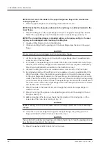
7. Mount the tube with the greater diameter, SA16, to the bevel gear with a hose clip
SA10. See Fig. 29.
SA14
Fig. 28.
SA10
SA14
SA16
Fig. 29.
8. Check that the motor-drive mechanism is in the EXACT position and that the position
indicator in the motor-drive mechanism shows the same position as the indicator inside
the top-cover of the on-load tap-changer.
EXACT position for the BUE is when the red indicator flag is in POSITION and the red
mark on the brake disc is aligned with the red mark on the brake pad. See Fig. 13.
EXACT position for the BUL is when the roller on the brake arm is in the notch of the
cam disc. See Fig. 14.
If out of position hand crank the motor drive mechanism to EXACT position according
to above.
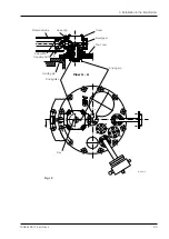
9. Open the cover of the gear box on the top cover of the on-load tap-changer. Check
that the key on the vertical shaft in the bevel gear is facing the earthing symbol on the
flange of the on-load tap-changer. See Fig. 30. If not, the multiple hole coupling must
be adjusted. Turn the vertical shaft until the key is facing the earthing symbol. Mount the
two screws and the locking nuts in the two holes of the coupling halves which are clos-
est to each other and tighten.
CAUTION
If the key is not in position as described above, the tap-changer operation will be too early in
one direction and too late in the opposite direction.
The motor-drive mechanism and the on-load tap-changer shall have the same indicated
tap position and the key in the bevel gear onto the on-load tap-changer shall be facing the
earthing symbol according to Fig. 30.
WARNING
The bevel gear contains moving gears. Be cautious!


