background image

4   

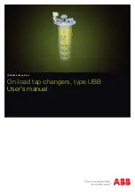
User's manual UBB


1ZSE 5492-156 en, Rev. 4

Introduction

The UB range of on-load tap-changers manufactured by ABB 
has been developed over many years to provide maximum 
reliability. The simple and rugged design gives a service 
life equal to the service life of the transformer. Minimum 
maintenance is required for trouble-free operation. The only 
parts requiring maintenance are contacts that might need 
replacement during the service life, the insulating oil and the 
motor-drive mechanism.

The design allows ready access to all parts, making 
inspection and maintenance quick and simple.

The on-load tap-changers, type UB, is housed in the 
transformer tank. The motor-drive mechanism, type BUE or 
BUL, is attached to the transformer tank and connected to 
the tap-changer by means of drive-shafts and a bevel gear.

Safety warnings

The following warnings and notes are used in the manual:

WARNING

WARNING indicates an imminently hazardous 
situation, which if not avoided will result in death or 
serious injury. This signal word is to be limited to the 
most extreme situations.

WARNING also indicates a potentially hazardous 
situation, which if not avoided could result in death or 
serious injury.

CAUTION

CAUTION indicates a potentially hazardous situation, 
which if not avoided may result in minor or moderate 
injury. It may also be used to alert of unsafe practices.

CAUTION may also indicate property-damage-only 
hazards.

Safety precautions

WARNING

Personnel operating and inspecting the tap-changer 
must have good knowledge of the apparatus and 
must be aware of the risks pointed out in this manual.

Personnel making electrical connections in the motor-
drive mechanism have to be certified.

WARNING

Small amounts of explosive gases might come out 
from the breathing devices (dehydrating breather 
or one-way breather). Make sure that no open 
fire, hot surfaces or sparks occur in the immediate 
surroundings of the breathing devices.

CAUTION

After a trip from a supervisory device, an inspection 
must be made by a specialist. The diverter switch 
housing must be drained and the diverter switch lifted 
and carefully investigated before the transformer is 
reenergized.

Summary of Contents for UBB

Page 1: ...On load tap changers type UBB User s manual 1ZSE 5492 156 en Rev 4...

Page 2: ...ntative ABB makes no warranty or representation and assumes no liability for the accuracy of the information in this document or for the use of such information All information in this document is sub...

Page 3: ...d the electrical connection are correctly realized by the manufacturer of the transformer e g in compliance with our Installation Instructions and EMC Directive 89 336 EEC regarding the intrinsic char...

Page 4: ...death or serious injury This signal word is to be limited to the most extreme situations WARNING also indicates a potentially hazardous situation which if not avoided could result in death or serious...

Page 5: ...t in the shaft Crank in the desired direction as per the information plate above the shaft The number of turns for one step is also shown on the rating plate When the handcrank is inserted all electri...

Page 6: ...etermined with the help of this information Turn the control switch to the LOWER RAISE position Check that the motor also works properly in that direction the position indicator decreases increases on...

Page 7: ...g after about 2 litres of oil have been sucked out from the tap changer 3 Shut the air release valve and the oil valve and disconnect the pump 4 Open the conservator valve and an appropriate gas cushi...

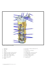
Page 8: ...ver selector fixed contacts 7 Selector switch fixed contacts 8 Selector switch moving contacts 9 Selector switch shaft 10 Bottom drain screw 11 Bottom 12 Valve R for filling and draining of oil 13 Top...

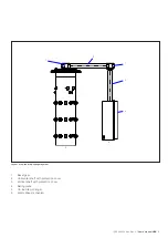
Page 9: ...ser s manual UBB 9 1 Bevel gear 2 Horizontal shaft with protection cover 3 Vertical shaft with protection cover 4 Rating plate 5 On load tap changer 6 Motor drive mechanism Layout of on load tap chang...

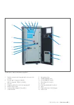
Page 10: ...ch 5 RAISE LOWER switch 6 Outgoing shaft 7 Lamp 40 W socket E27 8 Lifting eye 9 Counter 10 Tap change in progress indicator 11 Position indicator with drag hands for max and min position 12 Shaft for...

Page 11: ...ss White in position 3 Counter 4 Outgoing shaft with multi hole coupling half 5 Shaft for hand crank 6 Locking device prepared for padlock 7 Option Outlet 8 Emergency stop 9 RAISE LOWER switch 10 LOCA...

Page 12: ...opyright 2013 ABB All rights reserved 1ZSE 5492 156 en Rev 4 2013 04 15 ABB AB Components SE 771 80 Ludvika Sweden Phone 46 240 78 20 00 Fax 46 240 121 57 E Mail sales se abb com www abb com electrica...

Reviews: