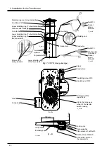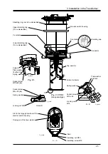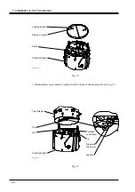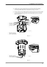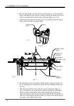
d. Lift the tie-in resistor unit against the tap selector and connect the potential
connection with the removed screw and washers, see Figs. 14 and 15.
e. The pin in the tap selector shaft must be in position to fit in the slot of the potential
switch shaft.The lip in the potential switch cylinder shall fit in the cut of the tap
selector, see Fig. 14.
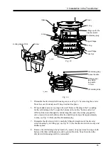
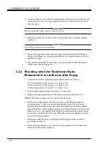
Fig. 15.
3 Installation in the Transformer
29
Potential connection
to the potential switch
Insulating nut
Insulating bolt
Potential connection
to the current collector
TC_00177
Cut
Lip
Screw
Washers
TC_00174
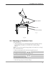
Fig. 14.


