44
4 Drying
The on-load tap-changer is dried together with the transformer using one of the
following processes: alternating hot-air and vacuum or vapour-phase at a temperature
of max. 135 °C (275 °F).
4.1 Observations before Processing
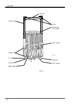
1. If not earlier done, lift the diverter switch out from the housing, see section 3.2.1
steps 5 and 7. The pressure relay with its test vent and the oil filter, if any, should
be dismantled and kept protected from dust e.g. in a plastic bag or in their original
packing.
2. Do not expose the diverter switch housing to any pressure difference between
inside and outside during the vapour-phase process. During the hot air and
vacuum process, the maximum permitted pressure differential is 100 kPa at a
temperature of 135 °C (275 °F).
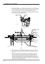
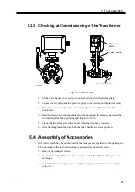
During the vapour-phase process the bottom valve of the diverter switch housing
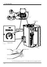
should be open. To open the bottom valve, proceed as follows, see Fig. 24:
a. Remove the plug on top of the oil draining tube, see Fig. 24.
b. Use the bottom valve key (DS16) through the oil draining tube, see Fig. 24.
c. Turn the valve anticlockwise to its stop, approximately 6 turns.
d. Remount the plug.
e. Remove the O-ring in the lower flange (for mounting on active part only)
before process.
4.2 Observations after Processing
CAUTION
To avoid seizing, do not operate the on-load tap-changer, neither during the drying
process nor afterwards, until it is filled with oil.
1. Make sure that all liquid has been drained from the diverter switch housing when
vapour-phase process has been carried out. Close the bottom valve, see section
3.2.3, step 10.
CAUTION
Make sure the bottom valve key is removed after the valve has been closed.
2. The cleats, on the upper section of the tap selector, holding the conductors between
the diverter switch housing and the tap selector should be retightened (tightening
torque 15 Nm) and locked by method specified by the transformer manufacturer
for similar screw joints.
4 Drying


