5 Final Assembly
57
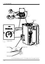
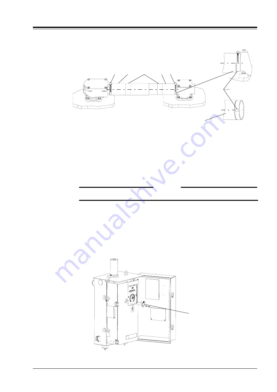
Slot facing
downwards
SA25
SA10 SA24
SA23 SA10
SA23
Fig. 42e.
8. Push the two protective tubes on to the bevel gears and clamp them with hose
clips, SA10, see Fig. 42e.
NOTE:
The slot of the protective tube SA23 shall be facing downwards.
Apply the self-adhesive information plates SA25 around the tubes on about the
middle of the tube length.
WARNING
The bevel gear contains moving gears. Be cautious!
5.2.3 Before Operation
1. Check again that the on-load tap-changer and the motor-drive mechanism are
in the same position.
2. Remove the locking device of the motor-drive mechanism, see Fig. 43.
TC_00148
TC_00151
Locking device
Fig. 43. Locking device of motor-drive mechanism

