59
5 Final Assembly
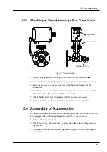
5.3.3 Checking at Commissioning of the Transformer
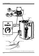
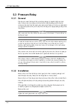
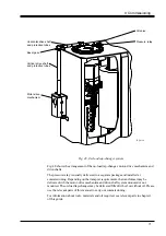
Valve handle
Test tap (R 1/8)
Information
plate
TC_00264
Fig. 44. Pressure relay
1. Set the valve handle in the test position as shown on the information plate.
2. Connect the air pump and the pressure gauge to the test tap on the pressure relay.
3. Raise the pressure until the pressure relay trips the circuit breakers for the
transformer.
4. Read the pressure on the manometer and check against the pressure stated on the
information plate. Max. permitted deviation is ± 10 %.
5. Check that the alarm signal disappears when the pressure is lowered.
6. After finishing the check, turn back the valve handle to service position.
5.4 Assembly of Accessories
All details which have been removed for the transport are specified on the packing list.
The openings on the on-load tap-changer are sealed by transport covers.
1. Remove the transport covers.
2. Check the O-rings. Make sure they are pressed into the bottom of the groove on
the flanges.
3. Assemble all remaining accessories. Tightening torque for the nuts according to
section 1.8.

