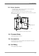
9 Commissioning
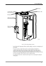
Horizontal drive shaft
and protective tubes
Bevel gear
Vertical drive shaft
and protective tubes
Motor-drive
mechanism
Pressure relay
Oil valve
TC_00139
Fig. 48. On-load tap-changer system
Fig. 48 shows the arrangement of the on-load tap-changer, motor-drive mechanism and
drive-shafts.
The pressure relay is usually delivered in a separate package and installed at
commissioning. Depending on the transport requirements, the transformer may be
delivered with the motor-drive mechanism and drive-shaft system mounted or not
mounted. The on-load tap-changer may be delivered filled with oil or without oil. Please
use the relevant parts of this manual to carry out commissioning.
For information about tools, materials and oil required, see relevant parts in chapter 1
of this guide.
71


