1 Introduction
1 Introduction
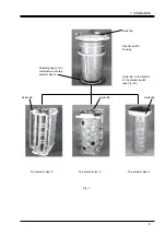
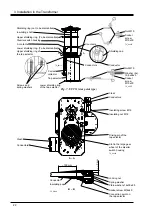
The arrangement of on-load tap-changers types UCC and UCD are shown in
Figs. 1 and 2.
A UCC on-load tap-changer has always tap selector IV. A UCD on-load tap-
changer has tap selector III or G.
To make transportation easy the on-load tap-changer is delivered in three main parts.
These are diverter switch housing, tap selector and motor-drive mechanism.
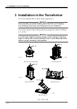
The on-load tap-changer is performed for cover-mounting and for yoke-mounting.
Cover-mounting means that the diverter switch housing is lowered through the hole in
the transformer tank and then bolted straight onto the transformer cover, and after that
the tap selector is mounted. Yoke-mounting means that the on-load tap-changer is
temporarily put on a fork located on the active part of the transformer. Yoke mounting
allows the transformer manufacturer to connect the windings to the on-load tap-changer
before drying and without having the transformer cover mounted. The
transformer cover is then lowered onto the tank, and the on-load tap-changer is lifted
and bolted to the cover. Please use the appropriate instruction for cover-mounting or
yoke-mounting in chapter 3.
At cover-mounting the diverter switch housing is installed on the transformer cover
before joining with the tap selector.
After the drying process of the transformer the motor-drive mechanism and bevel gear
are fitted to the transformer tank and the drive shafts are fitted to complete the
assembly of motor-drive mechanism, bevel gear and on-load tap-changer before oil
filling and testing.
The arrangement of the on-load tap-changer systems is shown in Figs. 2-2b.
Position numbers in the Installation Guide, for example SA11 (see chapter 5)
correspond with those in the packing list for the on-load tap-changer.
All instructions are for one on-load tap-changer unit. In case of more than one unit on
the transformer, carry out the same procedures for each unit.
9

