1ZSC000562-AAZ en
|
Installation and commissioning guide UCL/VUCL
27
3.4 Transformer ratio measurement
The transformer ratio measurement may be taken before or
after the drying process.
If it is taken before drying, no drive system is mounted. The
tap-changer thus must be operated directly on the shaft
coupling of the bevel gear on the upper flange. A special hand
crank can be ordered from ABB; see Section 1.2.
If it is taken after drying, it is advisable to do this when the
drive system is mounted, after final assembly (see Chapter 5),
to simplify operation of the tap-changer.
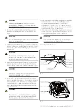
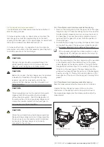
CAUTION
The tap-changer should be operated through the
whole operating range, both in the lower and raise
direction, when taking the ratio measurement.
CAUTION
Before the process, the tap-changer may be operated
a maximum of three times through the regulating
range as long as it is immersed in oil. After the
process, the tap-changer must be immersed in oil
before operating.
CAUTION
The end-positions must not be overrun during ratio
measurement. When operating the tap-changer
without the drive system, check the designation of
the end-positions on the single-phase diagram and
monitor the position indicator on the bevel gear to
avoid overrunning the end-position.
CAUTION
Check the voltmeter during tap-changer operations.
No rapid voltage drops may occur during operation.
If such drops occur, the diverter switch is installed
incorrectly or the tap-changer is not correctly
connected to the winding.
3.4.1 Transformer ratio measurement before drying
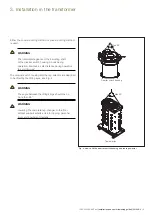
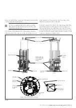
1. Remove the locking device from the gear unit on the upper
flange; see Fig. 22. Save the locking device for reuse after
transformer ratio measurement. Also remove the cover of
the bevel gear to access the position indicator. Save all
fasteners and the gasket for reuse. Note the position of
the tap-changer.
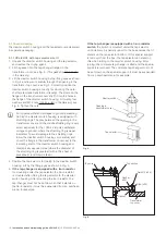
2. Operate the tap-changer by putting the special hand crank
on the shaft coupling of the bevel gear. Adjust the length
of the handle. Be careful not to damage the coupling.
When operating through the middle position on a tap-
changer with the change-over selector, the torque on
the hand crank will be higher.
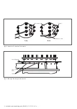
3. After the measurement, the tap-changer must be operated
in the direction and to the position shown in the single-
phase diagram as the delivery position. The right position
designation should be shown in the window in the position
indicator on the bevel gear of the tap-changer, and the
window should exactly face the red mark in the bevel gear
housing; see Fig. 12. Remount the locking device on the
bevel gear and the cover of the bevel gear. Carefully fit the
gasket.
3.4.2 Transformer ratio measurement after drying
Take this measurement after the drive system is mounted.
Operate the tap-changer by means of the motor-drive
mechanism, in the direction and to the position shown in
the single-phase diagram as the delivery position after the
measurement.
Fig. 22.
Locking device
UCL and VUCL.N or E
UCL and VUCL.T or B
Summary of Contents for UCL
Page 1: ...On load tap changers type UCL and VUCL Installation and commissioning guide 1ZSC000562 AAZ en...
Page 8: ......
Page 53: ......
Page 54: ......
Page 55: ......

