9
D.
ADNN-, or OJON- disconnectors
mounted on the side wall of the
cubicle
The operating device can be mounted on either the
left hand or right hand side of the disconnector. When
mounted on the left hand side it must be noted that
the direction of operation should be changed to anti-
clockwise closed, refer to point 5.h.
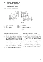
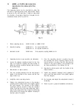
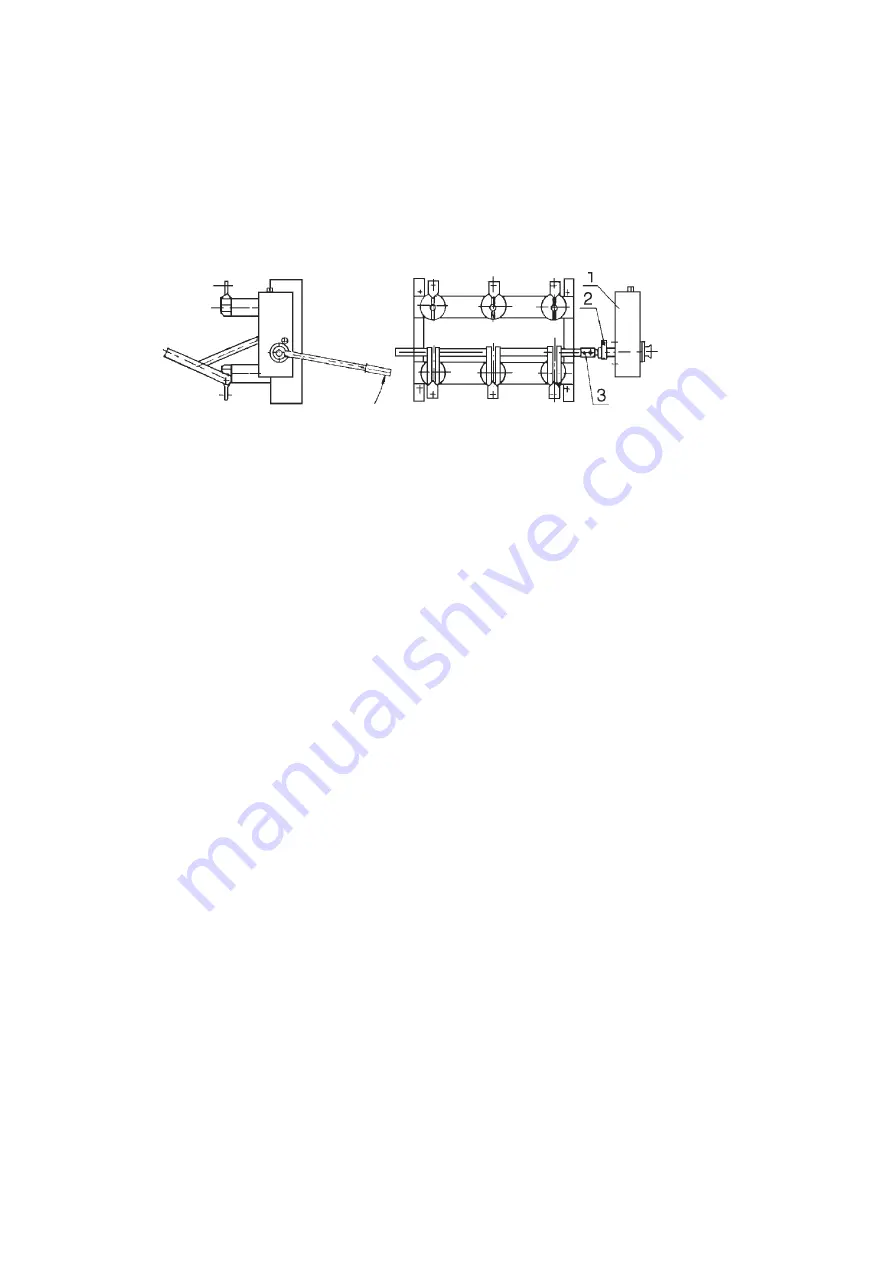
Fig. E
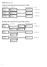
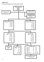
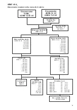
1. Motor operating device
UEMC 40 B2-, or UEMC 40 B1
2. Adjuster coupling
UEMC-ZL 9
for round shaft Ø 25
UEMC-ZL 10 for splined shaft Ø 25
3. Extension shaft
UEMC 242
fi t to adjuster coupling UEMC-ZL 10
1. Operating device in open position (as delivered).
2. Loosen the adjuster coupling screws to max. free
play. The adjuster coupling provides facility to
adjust the extreme positions exactly and to reduce
the control angle.
3. Disconnector in open position.
4. Turn the coupling adjuster and the disconnector
lightly in the direction of the arrow until the free
play is taken up.
5. Install the motor operating device.
6. Tighten one adjustment screw on the adjuster
coupling until the disconnector turns lightly against
the open stopper. The position of the adjuster
coupling's splines should be that the adjuster
screw is screwed out only a few millimeters, other-
wise the free play will not be enough for positioning
at the other end. Change the adjuster coupling to
another spline if required.
7. Free the operating device’s coupling ring A-4
and operate the motor operating device to the
closed position, ensuring that the disconnector
remains in the open position. The operation can
be made electrically or by rotating the nut.
8. Operate the disconnector with the handle to the
closed position.
9. Tighten the adjuster coupling's other adjustment
screw until the disconnector turns lightly against
the close stopper.
10. Test operate and adjust the adjustment screws if
necessary.
11. Refer to point 5, general installation instructions.
Summary of Contents for UEMC 40 A Series
Page 26: ...26 26 ...
Page 50: ...50 50 ...
Page 74: ...74 74 ...
Page 86: ...86 86 ...
Page 87: ...87 ...

