- 13 -
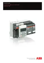
UMC100-FBP
Universal Motor Controller
UMC100-FBP
Technical Description
V 6
FieldBusPlug / Issue: 03.2012
DX111
1 C a 1 C b 2 C a 2 C b
READY
Diag
ERROR
In p u ts D I 24V DC
R e la y D O
230V AC / 1A
0V 24V DC
1DI0 1DI1 1DIZ
1DI2 1DI3 1DI4
1DO0 1DO1 1DOC
2DIZ 2DI5 2DI6
2DI7 AO+ AO-
2DOC 2DO2 2DO3
DX122
1 C a 1 C b 2 C a 2 C b
READY
Diag
ERROR
In p u ts D I 230V AC
R e la y D O
230V AC / 1A
0V 24V DC
1DI0 1DI 1DIZ
1
1DI2 1DI3 1DI4
1DO0 1DO1 1DOC
2DIZ 2DI5 2DI6
2DI7 AO+ AO-
2DOC 2DO2 2DO3
DX111-FBP
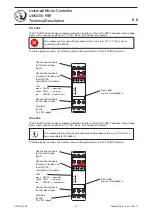
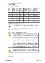
The DX111-FBP expands the input and output channels of the UMC100.
It provides eight digital inputs for 24 V DC, four relay outputs and a current output to drive an analogue
instrument.
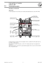
The following diagram shows the terminals and monitoring elements of the DX111-FBP module.
DX122-FBP
The DX122-FBP expands the input and output channels of the UMC-FBP.
It provides eight digital inputs 110 V AC - 230 V AC, four relay outputs and a current output to drive an
analog instrument.
The following figure shows the terminals and monitoring elements of the DX122-FBP module.
Connecting terminals
for the digital inputs
Connecting terminals for
the analogue output.
Connecting terminals
for the relay outputs
Front label,
e.g. for slave address
Terminals
for the
24 V DC supply
Connecting terminals
for communication with
the UMC100
and further IO modules.
Connecting terminals
for the digital inputs.
LEDs
green READY = operation
yellow DIAG
= warning
red
ERROR = module fault
Terminals
for the
24 V DC supply
Connecting terminals
for communication with
the UMC100
and further IO modules.
Connecting terminals
for the digital inputs.
LEDs
green READY = operation
yellow DIAG
= warning
red
ERROR = module fault
Connecting terminals
for the digital inputs
Connecting terminals for
the analogue output.
Connecting terminals
for the relay outputs
Front label,
e.g. for slave address
Summary of Contents for UMC100-FBP
Page 1: ...Technical Description Universal Motor Controller UMC100 FBP ...
Page 157: ......

