


PRIM AR Y TESTING
CURRENT S ENSORS
1VLG5000 17 C
21
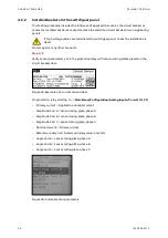
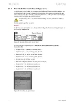
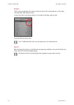
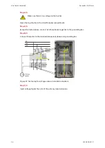
Step 2/5
Move two neighboring circuit breakers into the service position and close them.
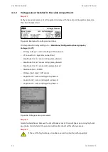
Default values of overcurrent, earth fault and unbalance protection functions can op-
erate the circuit breaker during primary injection. Disable all related protection func-
tions in the protection relay or disconnect the tripping coil (MO) from the negative
potential of power supply in the low voltage compartment before primary injection to avoid
unwanted tripping of the circuit breaker.
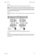
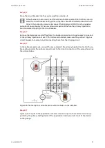
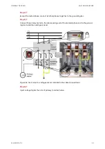
Step 3/5
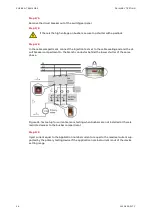
In the cable compartments, connect the injection device to the cable sealing end of the same
phase.
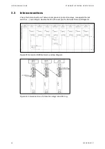
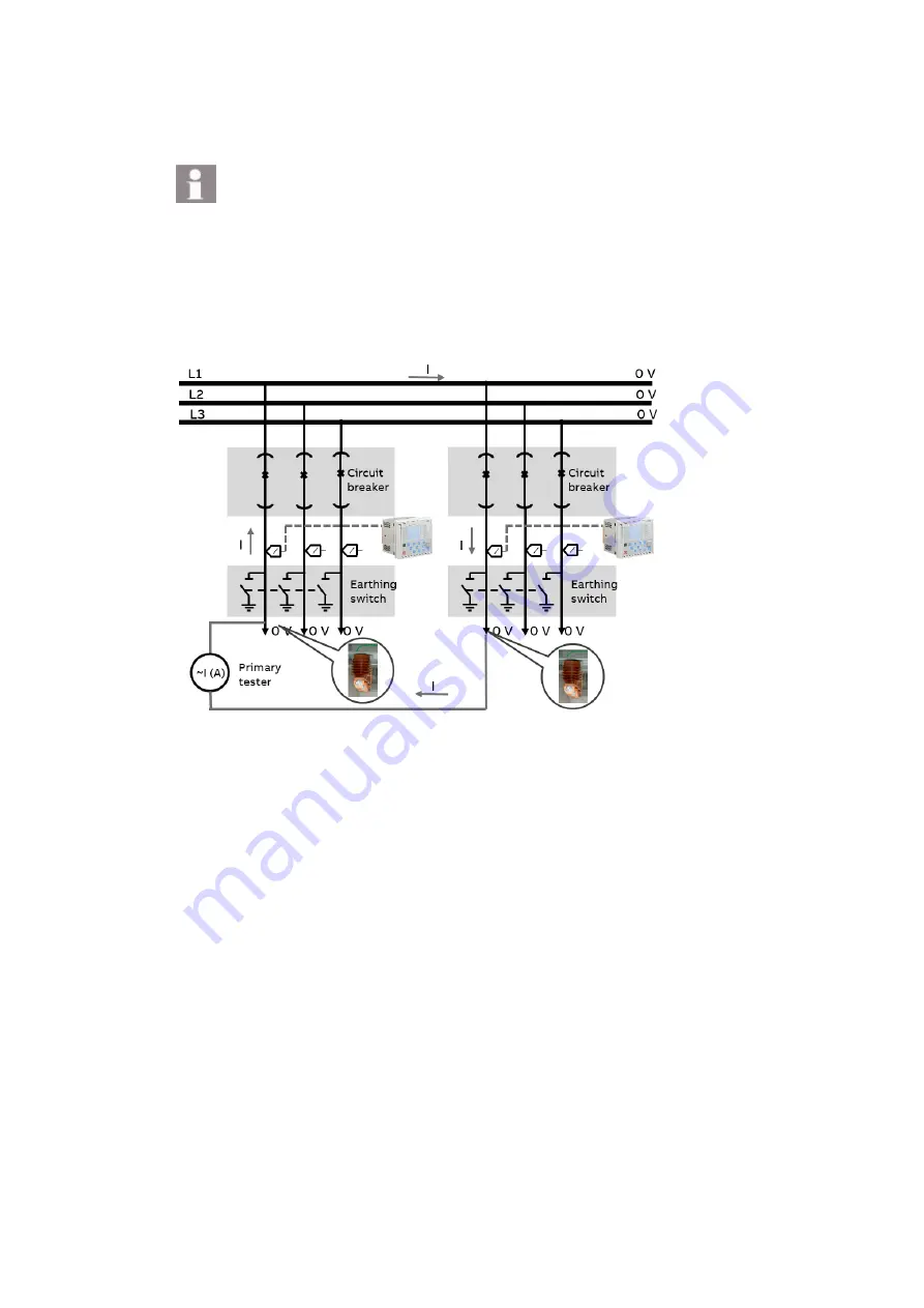
Figure 31 Primary test setup for current sensors when busbars are installed
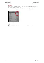
Step 4/5
Inject a current equal to the application nominal current or equal to the maximal current sup-
ported by the primary testing device if the application nominal current is out of the device
setting range.
Summary of Contents for UniGear Digital
Page 1: ...DISTRIBUTION SOLUTIONS UniGear Family UniGear Digital Commissioning and testing Guide...
Page 2: ......
Page 3: ...DISTRIBUTION SOLUTIONS UniGear Family UniGear Digital Commissioning and testing Guide...
Page 6: ......
Page 10: ......
Page 12: ......
Page 96: ......
Page 98: ...Visit us www abb com mediumvoltage Document Number 1VLG500017 Rev C...