


LIST O F FIGUR ES
III
List of Figures
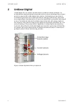
Figure 1: UniGear Digital and its key components
.................................................................................
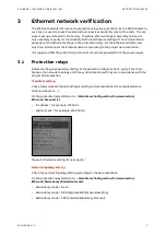
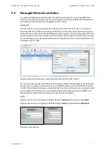
Figure 2: IP address setting for rear port(s)
............................................................................................
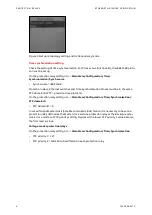
Figure 3: Network topology setting and its Redundancy mode
........................................................
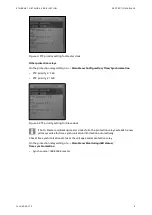
Figure 4: PTP priority setting for Master clock
......................................................................................
Figure 5: PTP priority setting for Slave clock
.........................................................................................
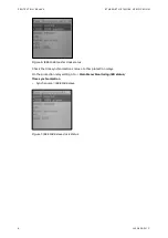
Figure 6: IEEE 1588 master clock status
..................................................................................................
Figure 7: IEEE 1588 slave clock status
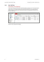
Figure 8: Properties dialogue of discovered Ethernet switch by AFS Finder
..................................
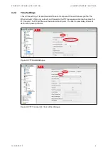
Figure 10: Port configuration dialogue
....................................................................................................
Figure 11: PTP Global dialogue
Figure 12: PTP Transparent Clock Global dialogue
...............................................................................
Figure 13: Transparent clock Port dialogue
...........................................................................................
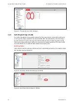
Figure 14: Switching VLAN Global dialogue in AFS67x
........................................................................
Figure 15: Switching Global dialogue in AFS66x
...................................................................................
Figure 16: VLAN Configuration dialogue
................................................................................................
Figure 18: VLAN Configuration dialogue (Port 6 is connected to SCADA)
.....................................
Figure 20: Example of HSR Network overview diagram
.....................................................................
Figure 21: Interconnection of protection relays into HSR ring
..........................................................
Figure 22: Example of PRP network overview diagram
.......................................................................
Figure 23: Interconnection of protection relays into PRP networks
................................................
Figure 24: Example of Plant Structure in PCM600
...............................................................................
Figure 25: GOOSE / SMV alarm is activated on a configurable LED
................................................
Figure 28: Primary test system CPC 100 from Omicron
.....................................................................
Figure 29: Example of a current sensor label
.......................................................................................
Figure 30: Current sensor parameters
...................................................................................................
Figure 31 Primary test setup for current sensors when busbars are installed
..............................
Figure 33: Example of a current sensor label
.......................................................................................
Figure 34: Current sensor parameters
...................................................................................................
....................................................................................
Figure 37: Example of a current sensor label
........................................................................................
Figure 38: Current sensor parameters
...................................................................................................
Figure 39: Test setup for current sensors when busbars are not installed
....................................
Figure 41: Example of a voltage sensor label
.......................................................................................
Figure 42: Voltage sensor parameters
...................................................................................................
Figure 43: Test setup for voltage sensors installed in the cable compartment
Figure 44: Measurements view, injected phase 1
................................................................................
Figure 45: Example of a voltage sensor label
.......................................................................................
Figure 46: Voltage sensor parameters
..................................................................................................
Figure 47: Test setup for voltage sensors installed on busbars
......................................................
Figure 48: Measurements view, injected phase 1
................................................................................
Summary of Contents for UniGear Digital
Page 1: ...DISTRIBUTION SOLUTIONS UniGear Family UniGear Digital Commissioning and testing Guide...
Page 2: ......
Page 3: ...DISTRIBUTION SOLUTIONS UniGear Family UniGear Digital Commissioning and testing Guide...
Page 6: ......
Page 10: ......
Page 12: ......
Page 96: ......
Page 98: ...Visit us www abb com mediumvoltage Document Number 1VLG500017 Rev C...