44
ABB Power Distribution
6
Operation of the ZS1 switchgear
The relevant work and operating procedures are to
be carried out carefully by trained specialists familiar
with the installation, taking into account all relevant
safety regulations according to DIN VDE/IEC and
other relevant professional bodies, and other local
and works regulations and instructions. Special
attention should also be paid to full compliance with
VDE 0105 (Operation of electrical installations).
6.1
Start-up
6.1.1
Preparatory work
(Figures 3/10, 3/20 and 6/20)
In preparation for commissioning, the following
work should be carried out prior to connection with
the high-voltage power supply:
• Check the general condition of the switchgear
for detrimental circumstances of all kinds.
• Perform a visual examination of the switching
devices, withdrawable parts, isolating contacts,
insulating parts, etc.
• Check the connection of the main earthing bar
with the station earthing conductor (DIN VDE
0141).
• Check the paintwork for damage and touch up
as described in section 7.4.1 where necessary.
• Remove all material residues, foreign bodies and
tools from the switchgear.
• Clean the switchgear, rubbing down insulating
parts with a clean, soft, non-fraying and dry
cloth. Remove greasy or adhesive dirt as
described in section 7.3.
• Properly refit all covers, etc., removed during
assembly and testing processes.
• White transport caps 13.9 on the poles of vacuum
circuit-breakers, where fitted, must be removed.
• Pole tube caps 13.10 may be fitted to the
vacuum circuit-breakers in certain switchgear
installations and with breakers of certain types.
Their proper fit should be checked.
• Lifting lugs 13.13 for high-current circuit-
breakers, if still fitted, must be removed.
• Perform AC voltage testing on the main circuits
to VDE 0670, Part 6 (IEC 60298) as far as
necessary. Pay special attention during this
procedure to voltage transformers and cables
etc. A testing and earthing withdrawable part
142 can be used to establish the connections.
• Switch the auxiliary and control voltage on.
• Carry out test operations of switching devices
manually or by electrical control, and simul-
taneously observe the relevant position
indicators.
• Check mechanical and electrical interlocks for
effectiveness, without using force.
• Set the protective devices in the panel to the
required values, and check their functioning with
test equipment.
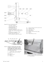
• In panels with an additional ventilation system
due to increased ambient temperature
according to section 1.3 (figures 6/21 and 6/22),
the flap 20.3 hanging in partition 20 must loosely
rest against leaf spring 20.4 (with the centrifugal
fan at a standstill if fitted):
To check:
– Insert a suitable screwdriver through opening
20.5 in horizontal partition 20 and into bracket
20.6 on flap 20.3.
– Swing flap 20.3 upwards and allow it to rest
loosely again on leaf spring 20.4.
– If the flap is in the blocked position, use the
screwdriver to press leaf spring 20.4
downwards by approx. 5 mm to release the
block before swinging the flap.
– If any centrifugal fans controlled in relation to
primary current are fitted, also check that they
function correctly.
• On motor-driven withdrawable parts, check the
direction of rotation of the travel motors as
described in section 7.5.1.
• For any further questions on the functions of the
withdrawable circuit-breaker part and its testing,
see section 7.5.
• Instruct the local operators in the fundamental
details of regular handling of the switchgear.
• Check on the operational readiness and
switching status of electrical systems upstream
and downstream from the switchgear.
From areas bordering on the switchgear, in
accordance with responsibilities, check on the
following where applicable:
• Power cables
• Auxiliary cables
• Auxiliary power source
• Remote control
• Entire earthing installation, according to DIN
VDE 0141
• Switchroom equipment
• Switchroom condition.
6.1.2
Start-up
• Comply with all relevant safety regulations.
• Ensure that the circuit-breakers and switch-
disconnectors in the switchgear are in the OFF
position.
• Remove any existing earthing and short-circuit-
ing connections in the critical switching area.
• Energize the feed cables.
• Connect the switchgear, step-by-step, observing
the signals and indicators.
Summary of Contents for UniGear ZS1
Page 66: ...ABB Power Distribution 67 ...


