background image

ABB Power Distribution

59

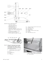
Checking of the readiness for operation can
be carried out as follows:

a) Load-dependent functional test with

controllable primary current injection of the
relevant instrument transformer. At current
rise:

1. to approx. 70% of the rated instrument

transformer current, the fan must start,

and

2. to 80 % of the rated instrument

transformer current, the fan must have
reached the required minimum air flow.
Corresponding monitoring/signalling by
the wind vane with microswitch.

b) Basic checking with temporary operation of

the centrifugal fan with an external power
supply of 220 V AC.

c) In both cases, check for unimpeded normal

running of the fan and listen for any unusual
bearing noise. Remove any dirt on the fan
rotor.

d) Check the unimpeded function of the wind

vane and microswitch by starting the fan
several times.

e) The wiring to the removable horizontal

partition 20 can be disconnected behind
the right-hand side duct cover 43.4 (figure
3/13). Observe the circuit diagram and
carefully reconnect the wiring on
completion.

Caution:

 instrument transformer circuit.

• With regard to the switching devices, their sepa-

rate Instruction manual should be observed.

• Check all switchgear accessories and auxiliary

facilities (e.g. storage batteries).

• No external discharge may occur on the

surfaces of equipment at operating voltage. This
can, for example, be detected by characteristic
noises, a clearly perceptible smell of ozone, or
visible glowing in the dark.

• Visual checking of the contact system. We

recommend to turn alternately the contact
system in order to clean the inner contact points
of the contact system.

The contact points should be cleaned if signs of
unperminable overheating (discoloured surface)
are visible (see section 7.4).

• If irregular conditions are detected, then cor-

responding repair measures should be initiated.

7.3

Servicing

If, on the occasion of an inspection in accordance
with 7.2, the necessity of cleaning measures has
been established, proceed as follows:

• Before cleaning, where required, the working

area must be switched off and secured against
reconnection in accordance with the „Safety
Regulations“ specified by DIN VDE/IEC.

• Cleaning the surfaces in general:

– Weakly adhering dry dust deposits with a soft

dry cloth.

– More strongly adhering grime with mildly

alkaline household cleanser or with Rivolta
BWR 210.

• Cleaning insulating surfaces and conductive

components:

– Minor pollution with Rivolta BWR 210.

– Strongly adhering pollution with Cold cleanser

716.

• Observe the manufacturers’ directions and in

particular ABB Instruction manual BA 1002/E
and BA 1006/E on safety at work.

• Wipe down after cleaning, using clean water,

and dry properly.

• Should external discharges occur as a result of

condensation, application of a thin silicone film
on the surface concerned is often effective as a
temporary remedy. It is advisable to request
advice from the ABB after-sales service
department on permanent solutions to such
unusual problems.

7.4

Repair

7.4.1

Switchgear in general

Repair of surface damage:

• Carry out repair work immediately after a defect

has been discovered.

• Completely remove all rust from damaged paint-

work areas on steel sheet and other steel parts
by mechanical means, e.g. with a wire brush.

Lightly grind the surrounding paint coat and care-
fully degrease the entire area. Then immediately
apply an anti-rust primer and, after an appropriate
hardening time, apply the top coat. Only use
suitable and compatible paint products.

Apply the top coat in standard colour RAL 7035,
or the relevant special colour.

Summary of Contents for UniGear ZS1

Page 1: ...ABB Power Distribution 1 ZS1 Air insulated medium voltage switchgear 12 kV 17 5 kV Instruction manual BA 372 04 E ...

Page 2: ...ion manual accessible to all persons concerned with installation operation and maintenance The user s personnel are to act responsibly in all matters affecting safety at work and the correct handling of the switchgear If you have any further questions on this instruction manual the members of our field organization will be pleased to provide the required information That s why our instruction manu...

Page 3: ...lse floor 24 5 3 Erection of the panels 24 5 4 Installation of the busbars 25 Contents Page 5 5 Installation of the top mounted boxes 25 5 5 1 Voltage transformer for busbar metering 25 5 5 2 Earthing switch for busbar earthing 26 5 6 Pressure relief ducts 26 5 7 Connection of the cables 26 5 7 1 Power cables 26 5 7 2 Control cables 27 5 8 Earthing of the switchgear 27 5 9 Laying the ring circuits...

Page 4: ...7 5 5 Testing of interlock conditions 62 7 6 Tests on the panel 63 7 6 1 Auxiliary switch settings on the earthing switch 63 7 7 Spare parts auxiliary materials lubricants 63 7 7 1 Spare parts 63 7 7 2 Auxiliary materials lubricants 63 We reserve all rights to this publication Misuse particularly including duplication and making available of this manual or extracts to third parties is prohibited T...

Page 5: ...ing conditions 1 3 1 Normal operating conditions The switchgear are basically suitable for normal operating conditions for indoor switchgear and controlgear in accordance with VDE 0670 Part 1000 IEC Publication 60694 The following limit values among others apply Ambient temperature Maximum 40 C Maximum 24 h average 35 C Minimum according to 5 C minus 5 indoor class Humidity VDE 0670 Part 6 amends ...

Page 6: ... Rated short time current 2 3s kA 50 40 Auxiliary voltage V DC1 60 110 120 AC 110 220 1 Special DC voltage on request 2 Take the short circuit withstand capability of the instrument transformers into account separately For data on the individual switching devices see ABB switchgear handbook or the instruction manual for the switching device concerned as listed under 7 1 2 2 Resistance to internal ...

Page 7: ...e 1600 A mm 1000 1000 Depth Dimension c mm 13001 13001 1 1350 mm for rated tee off currents of 4000 A 2 Height of the control cabinet is 705 mm A V a b c The minimum ceiling height in the switchroom is 3000 mm Further details of the switchroom design can be found in figures 5 1 to 5 4 Weights Feeder panel including withdrawable circuit breaker part Weight kg Rated current Rated short time current ...

Page 8: ... which remains between these walls as a result of the design when the panels are joined together In the case of the duplex version with a rated short time current of up to 31 5 kA a swivelling lever cap is used instead of the three screw caps The door of the control cabinet has a catch fastener lock The enclosure is completed by top mounted pressure relief flaps which are according to the rated te...

Page 9: ...D4 the withdrawable assembly 13 15 the isolated contact arm 4 2 with the contact system 4 3 and the control wiring plug 10 2 The withdrawable assembly 13 15 and the circuit breaker are coupled via a multipole control wiring plug connection 10 3 The withdrawable assembly establishes the mechanical connection between the panel and the circuit breaker The fixed part is connected to the panel by forki...

Page 10: ...ndary devices are not intended for door installation they are mounted on perforated metal sheet 37 3 This is stored folded up to enable any subsequent changes to the wiring In the lower part of the control cabinet three rows of terminal strips are on the swivelling terminal strips holder 37 4 and below these auxiliary switch 10 4 for the control wiring plug is easily accessible For doors in which ...

Page 11: ...connected position to the service position electromecha nical2 interlock 3 4 3 Locking devices Figures 3 7 3 17 3 18 and 6 16 The shutters 12 1 can be secured independently of each other with padlocks when the withdrawable circuit breaker part has been removed Access to the drive shaft of the earthing switch can be restricted with a padlock Access to the circuit breaker compartment and the cable c...

Page 12: ...arrestors and pressure relief duct 4 Incoming feeder 12 kV 2000 A 31 5 kA with busbar earthing switch in top mounted box 5 Incoming feeder 12 kV 4000 A 40 kA with insulated busbar capacitance grading device 6 Busbar sectionalizing 12 kV 2500 A 40 kA with earthing switch 7 Bus riser 12 kV 2500 A with withdrawable metering unit and earthing switch 8 Busbar metering 12 kV 40 kA with withdrawable mete...

Page 13: ...switchgear in two rows Busbar sectionalizing connection with insulated busbar capacitance grading device 1 Busbar sectionalizing 2500 A 2 Bus riser panel with withdrawable metering unit 1800 h 1 2 1 Dimension dependent on switchroom volume and short circuit current 2 Minimum dimensions are specified by the manufacturer Make allowance for the floor thickness 2 1 ...

Page 14: ...bution 15 Figure 3 4 ZS1 Duplex switchgear 12 kV 1000 A 31 5 kA Double busbar switchgear according to the two breaker method 1800 1300 1300 50 50 1200 1200 2608 a Installation front to front b Installation back to back ...

Page 15: ...r compartment C Cable compartment D Control cabinet 6 Earthing switch 7 Current transformer 8 Voltage transformer 9 Intermediate wall 9 3 Busbar rear wall 12 Mounting plate 12 1 Shutter 13 Withdrawable circuit breaker part 17 Floor covering 20 Horizontal partition 20 2 Air vents 20 3 Flap 43 Duct cover 49 1 Pressure relief flap expanded metal 49 2 Pressure relief flap steel sheet ...

Page 16: ...operating mechanism 20 Horizontal partition 38 Lever for operating the shutters 41 Travel rail 43 1 Lateral covering of the external control wiring Figure 3 8 Circuit breaker compartment with withdrawable part 1250 A in disconnected position 10 2 Control wiring plug 13 17 Front plate Figure 3 9 Circuit breaker compartment with withdrawable part 2500 A in disconnected position 20 Horizontal partiti...

Page 17: ...rallel cabels 6 1 Position indicator of the earthing switch 14 Manual mechanism of the earthing switch 17 Floor covering 17 2 Reducer ring 23 Cable connecting bar 43 4 Lateral covering of the internal control wiring 44 Heating plate Figure 3 12 Cable compartment width of panel 650 mm with earthing switch voltage transformer and three parallel single conductor plastic cables 1 2 Control cable duct ...

Page 18: ...erminal strip holder swung upwards 10 4 Auxiliary switch for control wiring plug 37 4 Terminal strip holder 37 5 Screw for terminal strip holder 37 5 10 4 37 4 37 4 37 3 Figure 3 16 Mechanical plug interlock 10 1 Socket 10 2 Plug 32 Interlock lever Figure 3 17 Lock for earthing switch manual mechanism 14 9 Padlock 14 9 10 2 10 1 32 ...

Page 19: ...aker of the high current type VD4 13 9 Protective cap used during transport remove before putting into service 13 13 Lifting lug remove before putting into service Figure 3 19 View of the circuit breaker compartment with the withdrawable part removed and the shutters open 4 1 Contact pin 5 Isolating tulip 12 1 Shutter 43 3 Duct covering of the internal control wiring above 12 1 5 4 1 Figure 3 18 L...

Page 20: ...The panels are each fitted with four lifting lugs Transport panels upright Take account of the high centre of gravity Only ever carry out loading operations when it has been ensured that all precautionary measures to protect personnel and materials have been taken and using a crane fork lift truck and or manual trolley jack Loading by crane Fit lifting ropes of appropriate load capacity with shack...

Page 21: ... transport units protected from the weather in a dry place safe from damage Check the packaging for damage Check the drying agent see also section 4 2 on arrival of the consignment later at regular intervals When the maximum storage period starting from the date of packaging has been exceeded the protective function of the packaging can no longer be guaranteed take suitable action if intermediate ...

Page 22: ...inus 5 indoor temperature class must be ensured 5 2 Foundations Figures 5 1 to 5 5 The switchgear is preferably to be erected on a foundation frame set into the switchroom floor or on a raised false floor The guideline structural data listed below facilitate a rough calculation of the space required and preliminary planning of the room design for a switchgear project When the final construction do...

Page 23: ...ections are necessary for long switchgear When the screed is applied carefully backfill the foundation frame leaving no gaps The upper edge of the screed must be up to 3 mm below the upper edge of the frame Take account of the thickness of any additional floor covering The foundation frame must not be subjected to any injurous impacts or pressures particularly during the installation phase If thes...

Page 24: ...serving the grease film or cleaned with a metal free non woven cleaning cloth and evenly greased with a thin coat of Isoflex Topas NB 52 Prepare insulating covers 58 to suit the relevant busbar and thread them onto the busbar Install the busbars panel by panel Screw on the individual busbar elements one above the other depending on the system layout and in line with the flat tee off conductor 2 Fo...

Page 25: ...uched the anker of the blocking magnet 78 6 The auxiliary switch ON 78 4 must be operated before the toggle spring of the earthing switch has reached its dead point The push rod of the auxiliary switch must still have about 0 5 mm to go to the end position in the operated position 5 6 Pressure relief ducts Figures 3 1 and 5 18 The pressure relief duct is supplied dismantled in single parts The rea...

Page 26: ...nnect main earthing bar 19 with links 19 1 supplied in every panel Protection wiring connection of the foundation frame or the erected raised false floor respectively should be made Connect the earthing conductor coming from the earth electrode preferably via a removable bolted link for testing purposes to the main earthing bar 19 of the switchgear 5 9 Laying the ring circuits The ring circuits ar...

Page 27: ...ssure relief duct 18 Diverter Figure 5 1b Panels with and without toroidal core current transformers 1 1 1300 50 75 75 1 800 200 450 180 75 75 80 FT 650 FT 1000 FT 800 FT 650 575 925 725 600 200 200 450 80 160 130 145 130 145 130 160 147 78 5 131 5 86 124 78 5 154 5 175 150 150 175 4 5 3 1 2 A D C B A D C B 2 1 100 1350 1300 1450 154 5 78 5 124 86 131 5 78 5 147 160 130 145 130 145 130 160 200 180...

Page 28: ...ing the corresponding dimension2 must be adjusted accordingly 1 180 1 1 460 1075 2100 180 295 100 FT 200 H 200 3000 600 1150 FT 700 1350 530 H 2200 H 2595 9 14 10 13 8 2685 2050 650 920 100 16 Section E E 12 11 6 17 ZS1 25kA 200 100 80 2 2 180 1 1 1 2100 180 195 50 FT 200 H 200 3000 600 360 1050 FT 700 1300 1075 80 530 H 2200 H 2595 9 14 10 13 12 11 8 6 17 2685 ZS1 25kA 2050 650 870 50 16 Section ...

Page 29: ...1300 1 50 1 1 80 FT 650 FT 1000 FT 800 80 2 1 15 1175 145 2 15 2 15 2 15 3 1 2 FT 650 78 5 175 Figure 5 3 Guideline construction data for a raised false floor See figure 5 4 for sections FT panel width 1 Minimum dimension 2 Maximum dimension 3 When the minimum dimensions1 are changing the corresponding dimensions3 must be adjusted accordingly Figure 5 3b Panels with and without toroidal core curre...

Page 30: ...00 H 200 3000 1175 FT 700 1300 180 530 H 2200 H 2595 2650 9 14 10 12 11 8 6 7 145 2100 13 Section A A ZS1 25kA 1 180 1 1 50 FT 200 H 200 3000 1175 FT 700 1300 180 530 H 2200 H 2595 9 14 10 12 11 8 17 6 145 2100 13 Section C C 2050 650 870 50 16 2685 ZS1 25kA 1 180 1 1 2100 180 100 FT 200 H 200 3000 FT 700 1350 530 H 2200 H 2595 9 14 10 8 2685 2050 650 920 100 16 12 11 6 17 1175 245 13 Section E E ...

Page 31: ... frame 60 1 Foundation frame part 60 2 Foundation frame part 60 3 Link 60 4 Steel strip 60 5 Bracket 60 6 Dowel 60 7 Bolt M10x25 60 8 Jacking screw h Screed height 50 to 60 mm Top view Joining point View X 1075 FT 4 x FT View X 1075 FT a Foundation frame single panel b Foundation frame four panels Panel width FT 650 mm 800 mm or 1000 mm ...

Page 32: ... both sides in the central part of the walls 1 3 Aperture for the main earthing bar 1 4 Bore 1 5 Lifting lug 1 9 Threaded bush for switchgear assembly 1 11 Bore for control wiring bushing 24 27 Shim to be inserted above the opening when bolting together panels without busbar partitioning Figure 5 7 End panel of a switchgear with bolted on cover plates and rear wall 25 Rear wall 26 Cover plate 25 2...

Page 33: ...e conductor Observe the conductor arrangement a Bushings with busbar supports for busbar systems with double conductor Figure 5 8 Arrangement of the bushing plate and busbar bushing on the right hand panel side wall in bus tie panels View of the inside 2 Tee off conductor 3 Busbar section 9 3 Partition 28 Bushing plate 29 Busbar bushing 29 1 Busbar support for single conductor 29 2 Busbar support ...

Page 34: ... bag group part number GCE 800 6131R0103 3 5 Junction bag group part number GCE 800 6131R0104 3 6 Junction bag group part number GCE 800 6131R0105 3 7 Junction bag group part number GCE 800 6131R0106 3 6 3 3 1600 A 3150 A 3 6 3150 A 3150 A 3 5 3 2 2000 A 2000 A Rated tee off current 1600 A 3 2 3 7 4000 A 4000A 2 Rated busbar current 2000 A 3 4 ...

Page 35: ...bag group 29 Busbar bushing 29 2 Busbar support for double conductor 58 Insulating cover 58 1 Support for cover 58 5 Lid for 17 5 kV only 58 6 Washer DIN 125 58 7 Washer 25 mm diameter 29 58 29 2 28 1 X 58 1 58 5 58 6 58 7 58 1 Detail X 28 58 84 180 104 30 15 ø 108 Cutting location for tee off conductor system 2 x 100 x 10 20 23 60 32 15 58 1 45 38 ø 110 58 5 Cutting location for tee off conductor...

Page 36: ...ure non standard equipment shows the arrangement in panels without the busbar bushing plate 28 observe the notes in section 5 5 1 28 3 Partitioning non standard equipment on request 79 Top mounted box with voltage transformer 79 1 Intermediate box 79 2 Conductor tube 79 3 Reducer ring 79 28 3 79 2 79 3 79 1 ...

Page 37: ... in panels with busbar bushing plate 28 observe the notes in section 5 5 1 2 Tee off conductor 2 2 Connection bar 3 2 Spacer plate 5 mm thick B B A 2 2 A 3 8 3 2 3 2 Schnitt A A Schnitt B B 3 2 2 2 2 3 2 2 3 8 3 10 2 2 3 2 2 3 8 3 9 2 2 3 8 Tapped plate 3 9 Spacer plate 8 mm thick 3 10 Spacer plate 8 mm thick ...

Page 38: ... arrangement for the open position of the earthing switch 78 4 Limit auxiliary switch for earthing switch ON 78 5 Limit auxiliary switch for earthing switch OFF Figure 5 15 The earthing switch operating shaft is supplied loose when the top mounted boxes are removed for transport purposes View for the open position of the earthing switch with individual mechanism parts fitted in the positions for c...

Page 39: ...th earthing switch for busbar earthing 77 Top mounted box of the earthing switch 78 Operating mechanism box 78 1 Operating shaft 78 2 Slide 78 4 Auxiliary switch ON 78 5 Auxiliary switch OFF 78 6 Blocking magnet A A 77 78 1 78 SectionA A 78 5 78 4 78 2 78 6 ...

Page 40: ... 50 2 Ceiling height 3000 Ceiling height 3000 Figure 5 18 Pressure relief duct 9 3 Rear wall busbar compartment 25 Rear wall panel 49 3 Pressure relief flap behind 49 4 Plastic screw 50 1 Rear wall pressure relief duct 50 2 Front wall pressure relief duct 50 3 Attachment strips 50 4 Discharge grating 50 5 Absorber grating ...

Page 41: ...re 5 20 Cable termination with pluggable cable sealing ends 16 2 Cable sealing end size 1 16 3 Cable sealing end size 3 Cable connection bar for 3 parallel cables Panel width 650 mm 31 5 kA Cable connection bar for a single cable Cable connection bar for 3 parallel cables Panel width 800 mm 40 kA 16 2 16 3 P P 16 16 1 L1 L2 L3 535 ...

Page 42: ... 5 21 Cable termination in panels with a tee off current 1600 A 16 Cable sealing ends 16 1 Cable screen 11 5 49 2 49 4 Figure 5 22 Auxiliary switch for Ith limitation It may be necessary to move the auxiliary switches into their service position when the lifting lugs have been removed 11 5 Ith limiter 49 2 Pressure relief flap centre 49 4 Rupture bolt plastic ...

Page 43: ...uxiliary and control voltage on Carry out test operations of switching devices manually or by electrical control and simul taneously observe the relevant position indicators Check mechanical and electrical interlocks for effectiveness without using force Set the protective devices in the panel to the required values and check their functioning with test equipment In panels with an additional venti...

Page 44: ...en movement of the withdrawable part Briefly operate the electrical control for insertion or withdrawal the withdrawable part then automatically moves into the opposite position Observe the position indicator Note When the motor fails the withdrawable part can be moved in emergency manual operation If the drive motor fails during movement of the withdrawable part the withdrawable part must be move...

Page 45: ...ning of the charging condition symbols Discharged Charged Opening and closing the circuit breaker With the withdrawable part in the service position on and off switching operations should only be carried out with the doors closed Operate the local or remote electrical control Observe the position indicator The switching operation counter 13 5 for the circuit breaker is automatically incremented by...

Page 46: ...matically re charge I Open breaker 0 On Off Close breaker and I Off automatically re charge I Autoreclosing Off 0 sequence Activation via protection system On I automatic charging starts Off 0 Automatic charging 0 On Off Close breaker and I Off automatically re charge I Test switching of the circuit breaker without primary voltage can be carried out with the withdrawable part in the test position ...

Page 47: ...osing operation by turning the operating lever 122 through 180 in an anti clockwise direction up to the stop 6 2 4 Tee off earthing switch Figures 3 5 3 13 6 13 and 6 14 Earthing switches of type EK6 are used in ZS1 switchgear The earthing switch has a snap action closing mechanism which is independent of the rotary motion of the operating shaft Earthing switches 6 assigned to circuit breakers are...

Page 48: ...gy springs for the switch dis connector charged Emergency manual operation If a fault occurs in the motor operated mechanism the switch disconnector and earthing switch can be operated manually in emergencies with operating lever 122 in a similar manner to a switch witch manual mechanism To disengage the coupling to the motor operated mechanism first turn the operating lever 122 up to the relevant...

Page 49: ... panel door Secure neighbouring live areas e g possibly the feeder cables to prevent inadvertent contact b Handling for earthing at contact pins for rated currents above 1250 A Isolate the area to be earthed and secure against reconnection Remove the withdrawable circuit breaker part from the relevant panel Secure shutter 12 1 in front of the live contact pins with padlock 130 Bolt on actuating ba...

Page 50: ... of the capacitive voltage indication system if fitted Test procedure Only use phase comparators which comply with the IEC and VDE standards and are of suitable design for the indication system in the relevant switchgear Check the function of the unit immediately prior to use Ensure that the maximum permissible length of the measuring cables for each phase is not exceeded Connect the measuring cab...

Page 51: ... turn of the key to open or close a low voltage compartment 1 7 Figure 6 4 Operation and annunciation via digital control system 30 Measuring sockets LRM system 30 1 Protection cover for measuring socket 46 Bay control and protection unit REF542 1 8 46 30 30 1 Figure 6 3 Operation of a screw type door catch with the handle of the univeral key in the crank position 1 8 Screw type door catch on the ...

Page 52: ...test disconnected position 10 Control wiring plug connection closed 13 2 Mechanical ON push button 13 3 Mechanical OFF push button 13 4 Mechanical position indicator 13 5 Mechanical operating cycle counter 13 8 Charging condition indicator 13 11 Sliding handle connected to the catch in the withdrawable part base frame 18 Spindle mechanism 18 1 Square spigot 128 Charging lever Figure 6 6 Movement o...

Page 53: ...13 11 Sliding handle 13 12 Catch connected to sliding handle 124 Service truck 124 1 Height adjuster for the bench top 124 4 Release lever for the catch 124 3 124 13 13 11 Figure 6 11 Approaching the panel and positioning the service truck with the guide pins of the adjustable height bench top at the correct height for the catch to engage 124 1 Height adjuster 124 2 Guide pin 124 3 Catch Figure 6 ...

Page 54: ...ing switch in a circuit breaker panel 14 Manual operating mechanism for the earthing switch 14 1 Operating shaft 14 2 Slide 122 Operating lever 122 1 10 35 2 35 1 122 14 2 14 14 1 Figure 6 15 Panel with switch disconnector and fuse assembly 34 Switch disconnector 35 1 Switch disconnector operating mechanism 36 Insulating protection plate 43 4 Duct cover for internal wiring Figure 6 16 Lower shutte...

Page 55: ... example version 129 Shutter operating module 129 1 Actuating bars 1 pair removable Figure 6 18 Earthing at the bottom contact pins in a 650 mm wide panel 12 1 Shutter 129 Shutter operating module 133 3 Insulating rod 135 Warning label Figure 6 19 Earthing at the top contact pins in a 800 mm or 1000 mm wide panel 12 1 Shutter 142 Test earthing module 133 3 Insulating rod 135 Warning label 12 1 133...

Page 56: ...reakers due to increased ambient temperatures according to section 1 3 The internal flap is shown in the service position open Side view but without the wind vane with microswitch required with a fan 20 Horizontal partition fitted here with additional ventilation facilities for the circuit breaker 20 3 Flap 20 4 Leaf spring 20 5 Inspection opening 20 6 Bracket 20 7 Centrifugal fan Figure 6 22 Hori...

Page 57: ...uctions must also be observed together with this instruction manual in the individual cases concerned Vacuum circuit breaker type VD4 BA 352 E Vacuum circuit breaker type VD4 E BA 377 E Vacuum circuit breaker type VD4 High current BA 359 E Earthing switch type EK6 BA 304 E Switch disconnector type C3 BA 275 E If necessary further details can be taken from the technical documentation for the switch...

Page 58: ...f unperminable overheating discoloured surface are visible see section 7 4 If irregular conditions are detected then cor responding repair measures should be initiated 7 3 Servicing If on the occasion of an inspection in accordance with 7 2 the necessity of cleaning measures has been established proceed as follows Before cleaning where required the working area must be switched off and secured aga...

Page 59: ... the shank Fit arbor 127 or 127 2 onto the relevant contact arm 4 2 slide the contact system 4 3 over onto the contact arm and withdraw the arbor Check all contact fingers and annular tension springs for perfect fit Note The set installation position of contact arms 4 2 must not be changed by the improper use of force Replacement of the contact pins when the surface is damaged Figure 3 19 After an...

Page 60: ...4 2 then fitted immediately after the toggle spring mechanism has passed the dead centre position during rotation to the OFF position 7 5 Testing withdrawable parts with a VD4 type circuit breaker Figures 7 4 to 7 7 When functional tests are carried out on withdrawable parts compliance with the conditions listed below should also be checked 7 5 1 Motor driven withdrawable parts not standard Carry ...

Page 61: ...aker closed insertion of the withdrawable part towards the service position must be blocked after only half a turn of the crank in the clockwise direction and the travel motor on motor operated withdrawable parts must not be capable of being switched on With the earthing switch closed insertion of the withdrawable part towards the service position must be blocked after only two clockwise turns of ...

Page 62: ... be a run on of 0 5 mm in the fully operated position before the plunger reaches the stop for safety reasons 2 Limit auxiliary switch 11 4 for earthing switch ON must be operated immediately after the dead centre position of the toggle spring mechanism is reached in the closing process and the automatic quick closing process has started 3 Limit auxiliary switch 11 3 for earthing switch OFF must a ...

Page 63: ...k for manual operation and breaker front plate removed 10 3 Control wiring plug connector for withdrawable assembly 13 2 1 ON push rod 13 24 Roller 13 26 Lever 13 92 Angle lever 121 Hand crank 127 4 3 127 2 4 3 4 6 4 3 4 5 4 2 127 4 4 13 26 13 2 1 13 24 13 92 10 3 Figure 7 1 Fit the contact system back to front on the thin end of the arbor and slide it onto the thicker shank area 4 3 Contact syste...

Page 64: ...with auxiliary switches as installed covers removed 11 3 Auxiliary switch Q8S1 earthing switch OFF 11 4 Auxiliary switch Q8S2 earthing switch ON 14 1 Operating shaft 14 6 Blocking disc 14 7 Cam Y0 11 4 11 3 11 3 14 1 14 2 14 3 11 4 14 6 14 7 14 1 Figure 7 5 Detailed view of the opening and closing mechanism 13 2 1 ON push rod 13 25 Plastic cam 13 26 Lever Y1 Closing blocking magnet Figure 7 6 Manu...

Page 65: ...e part with travel motor viewed from the left hand side 13 24 Roller 13 25 Cam 13 26 Lever 13 27 Pin 13 90 Travel motor 13 91 Link rod 13 91 1 Bolt 13 91 2 Bolt 13 92 Angle lever 13 92 1 Bolt Figure 7 10 Mechanical interlock lock and release device circuit breaker with manually operated withdrawable parts 13 24 Roller 13 25 Cam 13 26 Lever 13 27 Pin 13 91 Link rod 13 91 1 Bolt 13 91 2 Bolt 13 92 A...

Page 66: ...ABB Power Distribution 67 ...

Page 67: ...I 24044 Dalmine Phone 49 0 21 02 12 12 30 Fax 49 0 21 02 12 19 16 Phone 39 035 395111 Fax 39 035 395874 E Mail calor info de abb com E mail sacetms tipm it abb com Internet http www abb de calor Internet http www abb com Instruction manual no GCEA 68 0372 P0102 Printed in Germany 03 01 250 PPI We reserve the right to make changes in the course of technical development ...

Reviews: