ABB Power Distribution
9
3
Panel design and equipment
3.1
Basic structure and variants
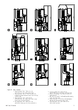
(Figures 3/1 to 3/5)
The basis for the ZS1 panel is the incoming/
outgoing feeder panel with vacuum circuit-breaker
using insertion technology. It is divided into busbar
compartment A, circuit-breaker compartment B,
cable compartment C and the control cabinet for
the secondary equipment D. Apart from this, there
are variants for all operating needs. The pictures 3/
1 to 3/5 show possible configurations of a panel
including electrical equipment.
For a busbar sectionalizing, two panels are
necessary, the coupling panel with the
withdrawable circuit-breaker part and a bus riser
panel (optional with busbar metering and earthing).
When setting up the switchgear in two rows, the
busbar sectionalizing can be combined with a bar
connection between the two sets of switchgear. In
equipment without busbar sectionalizing, a direct
bar connection between the busbars will be
established.
With ZS1 panels it is possible to set up a double
busbar installation in accordance with the two
breaker method. This duplex arrangement is
possible both with back to back or front to front
positioning.
Apart from this, panels with fixed-mounted
switch-disconnectors of type C3 (e.g. for feed to
a station service transformer) are provided.
Depending on rated short-time current and the
ceiling height of the circuit-breaker compartment, a
pressure relief duct on the panel would perhaps be
required.
Further details about the installation and equipping
of the switchgear can be obtained from the order
documents.
3.2
Enclosure and partitioning
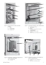
(Figure 3/5)
Enclosure and internal partitioning of the panels are
of high quality aluminium-zinc coated steel sheets,
2 mm thick. The three high voltage compartments
(busbar compartment circuit-breaker compartment
and cabel connection compartment) are equipped
with top-mounted, secured pressure relief flaps.
These open in the case of overpressure due to an
internal arc fault.
The front of the panel is closed off by pressure
resistant doors which open to an angle of almost
180
°
. Cable and circuit-breaker compartments
have their own doors equipped with sight glasses
made of security glass. Neighbouring panels are
partitioned from one another by the side walls of
each panel and the air cushion which remains
between these walls as a result of the design when
the panels are joined together.
In the case of the duplex version with a rated short-
time current of up to 31,5 kA a swivelling lever cap
is used instead of the three screw caps. The door
of the control cabinet has a catch fastener lock.
The enclosure is completed by top-mounted
pressure-relief flaps which are, according to the
rated tee-off conductor current, made of sheet
steel 49.2 or expanded metal 49.1 and below by
means of the floor-covering 17 made of sheet steel
which cannot be magnetized. The pressure-relief
flaps are secured with steel screws on one longitu-
dinal side and on the other longitudinal side with
plastic screws. In the case of internal overpressure,
the plastic screws are the point of rupture.
Part of the internal partitioning are the busbars-rear
wall 9.3, the intermediate wall 9, the mounting plate
12 with the shutters 12.1. and the horizontal
partition 20. The internal partitioning makes it
possible to have safe access to the circuit-breaker
and cable compartment even when the busbars
are live.
The control cabinet for the secondary equipment is
completely protected from the high voltage area
due to its steel-sheet casing.
On the front side, cover plates ensure a good
appearance and are mechanically and thermically
arc fault proof in case of such an event in the end
panel.
Doors and rear walls as well as the cover plates are
thoroughly cleaned and treated against corrosion
before receiving a high-quality double coating of
paint. The finishing coat is in the standard colour
RAL 7035 (special colours by agreement). The
stoving procedure completes the work and imparts
a notable insensitivity to impacts and corrosion.
3.2.1
Ventilation of the panels
(Figures 3/1, 3/5, 3/9)
For the purpose of ventilation in cases of certain
rated currents in the busbar and tee-off bars,
openings in the outer enclosure are necessary.
For incoming air to the circuit-breaker com-
partment, the horizontal partition is provided with
air-vents 20.2. The degree of protection IP4X and
safety in case of releases of hot gas caused by an
arc fault are provided by the flap 20.3 in the raised
false floor. In the case of outgoing air, the presssure
relief flaps are provided made of expanded metal
instead of clad metal sheets. The form and size of
the vents in the expanded metal provide the degree
of protection IP4X.
In the panel for tee-off rated current 4000 A, cross-
current blowers are installed for cooling purposes.
Summary of Contents for UniGear ZS1
Page 66: ...ABB Power Distribution 67 ...


