background image

UniGear 

type ZS2

                              UniSafe 36          

Installation and maintenance instructions for  
MV arc-proof air insulated metal-clad switchboards 


This  Manual contains general information needed for receiving, installation, commissioning, 
operation and maintainence of the switchboards. 
 
The trade name  of switchboards are referred as UniGear type ZS2 after june2004 


Summary of Contents for UniGear ZS2 UniSafe 36

Page 1: ... for MV arc proof air insulated metal clad switchboards This Manual contains general information needed for receiving installation commissioning operation and maintainence of the switchboards The trade name of switchboards are referred as UniGear type ZS2 after june2004 ...
Page 2: ... 3 Unpacking and transport 9 2 4 Cubicle s erection 10 2 5 Busbar assembly 11 2 6 Through Earth Bar 15 2 7 Cables termination 16 2 8 Final Tightening 17 2 9 Control Cables 17 2 10 End covers 18 2 11 Cleaning 18 3 PUTTING INTO SERVICE 18 4 OPERATING INSTRUCTION 19 4 1 Earthing Switch 19 4 2 Circuit Breaker HD 4 W 36 21 4 3 Withdrawable Voltage Transformer 23 4 4 Fixed Voltage Transformer cable circ...

Page 3: ...ne for operators is the front of the switchgear All operations must be made with the doors closed Only skilled and authorized personnel are allowed to open switchgear doors etc LOCAL RULES All operations described in this manual should be carried out by trained and specialized personnel The valid country standards and regulations and the safety procedures of the user organisation should also be fo...

Page 4: ...component Ratings apply for use in normal service conditions described in IEC 60694 para2 1 1 summarized as foll The ambient air temperature does not exceed 40degC The minimum ambient air temperature is 5degC The altitude does not exceed 1000m above sea level The ambient air is not significantly polluted by dust smoke corrosive and or flammable gases vapours or salt Degree of protection of persons...

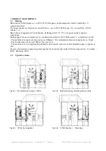
Page 5: ... 01 2005 en Page 5 of 25 Fig 1 2 5 Metering Complementary pair Fig 1 2 6 Circuit Breaker Feeder 1600 2000 2500A Width 2x1000mm including metering Fig 1 2 7 1600 2000 2500A Sectionalizer Fig 1 2 8 1600 2000 2500A Busriser 1 3 1200mm width version Fig 1 3 1 C B Feeder 630 1250 1600 2000 2500A ...

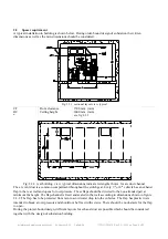
Page 6: ... steel of cubicles may have sharp edges inside and on the roof 2 1 Floor Check the floor regarding openings for the cables according to figure 2 1 1 and or 2 1 2 Check the floor level The deviations in height for the supporting surface to the cubicles must be less than 2mm m Otherwise the cubicles will require spacers to get a proper aligning Figure 2 1 1 Floor layout view typical D CL CR Rear cov...

Page 7: ...cubicles should be bolted to the floor similar to Fig 2 1 3 Base irons in the floor slab Similar to Fig 2 1 4 Framework flooring for switchgear The framework should be made with three longer sections one in the front one at the back and one in the middle along the switchgear Cross sections are to be fitted to support the sidewalls of the cubicles The cubicles should be fastened with bolts through ...

Page 8: ...el The arc vent duct is a common compartment throughout the switchgear Every 3rd or 4th cubicle has an exhaust flap in the rear wall and opens for overpressure These flaps should be directed to the non attended part at minimum 2m height The flap channel is fixed and sealed in the wall according to dimensions shown in figure 2 2 2 The flap has to be protected from rain to avoid water drop into the ...

Page 9: ...n be supplied upon specific request CAUTION The center of gravidity may vary according to apparatus installed in panels CAUTION Assure that the panel is not damaged tilted or dropped The lifting beam in fig 2 3 3 is not included in the delivery Consider min 1 5 ton lifting capacity for each 1000mm cubicle Fig 2 3 1 554685 801 Ordering number for the lifting handles Fig 2 3 2 Fig 2 3 3 For each swi...

Page 10: ... roof Before erection the highest point of the floor is identified The erection begins with the left hand cubicle which is placed in level with the highest point The cubicles are trestled if necessary in the front at the back and the middle along the switchgear This is made by one or more layers of thin steel plates If the cubicle will be mounted against the wall make sure that the bolts for the r...

Page 11: ...d against damaging of the insulation Damaged insulation must be renewed The PVC protective with air cushion will protect the insulated parts from damages also during transport and installation period Keep them on the busbars as long as possible until commisioning Busbar assembly work require cleanness as the dielectric strength will be decreased by metal dust etc Fig 2 5 2 Fig 2 5 3 Make sure the ...

Page 12: ...Page 12 of 25 Below are guide figures for busbars assembly Fig 2 5 4 Fig 2 5 5 Fig 2 5 6 Fig 2 5 7 Fig 2 5 8 Fig 2 5 9 Main busbar 2500A Circuit 1600 2000 2500A 2500A Main busbars should be installed while panel erection Otherwise access necessary both from the busbar compartment and the CB compartment ...

Page 13: ...nimum 3 of 7 full turns This will give 12mm adjusting margin for the aligned axis of the main busbars Tightening by the M10 bolt For dis assembly untighten the bolt by 10 15mm and hit by hammer to drop and release the expansion brass part Fig 2 5 14 Tee boot of transparent polycarbonate Fig 2 5 15 Tee boot on 2500A main busbar L3 right extremity Fig 2 5 16 Fasten with plastic strap after final ass...

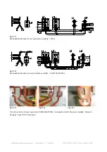
Page 14: ...14 of 25 Fig 2 5 17 Sectionalizer Busriser lower main bars assembly 1250A Fig 2 5 18 Sectionalizer Busriser lower main bars assembly 1600 2000 2500A Fig 2 5 19 Fig 2 5 20 Fig 2 5 21 View from front of lower main bars 1600 2000 2500A Sectionalizer left Busriser middle Detail of fixing by 2 pcs M12 bolts right ...

Page 15: ...earthing switches Those bars should be bolted together and the station earth system shall be connected to through earth bar Conical washers to ABB standard 9ADA334 must also be used throughout the earth bar connections The bare earth bar and the cubicle steelplates must not just touch either must be fixed with an air gap or bolted as connection Copper bars used for earth connection to the AluZinc ...

Page 16: ...m plate in the breaker compartment and or removal of the rear cover allows access to cables compartment Please consider that some commissioning tests part 3 are done with the power cables disconnected Fig 2 7 1 Fig 2 7 2 Fig 2 7 3 Fig 2 7 1 2 7 1 2 7 3 2 7 3 2 7 2 Cable comp width mm 1000 1000 1200 1200 2000 Cu conn bars Cu 2x40x10 2x80x10 4x40x10 4x80x10 4x80x10 Typical Cable lugs DIN46235 sqmm p...

Page 17: ...0 M12 M16 General assembly with steel bolts and nuts of min 8 8 property class mechanical and electrical connections 9 22 45 75 185 Main busbars assembly conductors supported by epoxy components with steel or brass nut threads with conical spring steel washer DIN6796 thread and bolt head contact surface LUBRICATED with grease or oil ref DIN 43673 4 5 10 20 40 80 2 9 Control Cables The control cabl...

Page 18: ...n and bushings should be wiped dry and vacuum cleaned 3 PUTTING INTO SERVICE All operations for putting into service must be carried out either by ABB personnel or other skilled personnel authorized by the user organization CAUTION Untill putting into service by authorized and skilled personnel the switchgear must not be energized The earthswitches must be closed all the time until the regular ene...

Page 19: ...tch CAUTION Earthing switch must not be attempted for operation when it is possible that a personnel may be in the cubicle OPEN AÇIK CLOSED KAPALI Fig 4 1 1 Left top Earth Switch Manover position indicator as should be seen on front Left bottom Earth switch position indicator as should be seen from lower window 7 Key lock for ESw at open position 8 Key lock for ESw at closed earthed position 9 Key...

Page 20: ...necessary the Esw in closed position 8 Opening the earthing switch Check that the circuit breaker is in test or withdrawn position The crank entrance 11 is open Insert the operating lever 13 This is not possible if the Esw is keylocked 8 at closed position Turn the lever anti clockwise 180º to open the earthing switch This is not possible if electrical interlocking coil is on Do not force Withdraw...

Page 21: ...d and lock the CB to the rails in the cubicle 8 Connect the multipole contact for the auxiliary circuits Attention The multipole connector fits only if the rating of CB fits the rating of cubicle 9 Check that the springs are loaded SF6 gas pressure is ok CB is open Auxiliary voltage present Electro mech interlocking YL2 blocks the racking when multi pole connector is inserted and control voltage i...

Page 22: ... 2 5 Handles for CB racking and Esw operation Fig 4 2 6 Front panel of HD4 at test position of CB Fig 4 2 7 CB and VT racking handle Fig 4 2 8 Multi pole auxiliary circuit plugged in and locked at service position of CB Fig 4 2 9 Front panel of HD4 at test position of CB Fig 4 2 10 CB position limit switches inside the LV compartment service connected test disconnected ...

Page 23: ...n the same order with a CB The same trolley and racking handle is used for CB s and VT s For possible replacement please note the exact electrical data and article number of the primary fuses during order correspondance Fig 4 4 1 VT in SERVICE connected position Fig 4 4 2 VT in TEST disconnected position Fig 4 4 3 VT WITHDRAWN removed position view of contact 4 4 Fixed Voltage Transformer cable ci...

Page 24: ...cant pasta T16865 A1 5gr ITSCB 1322 Klüber Isoflex Topas NB52 box RIVOLTA S K D 4002 box Some cleaning products include chemicals which affects the insulating materials busbar insulation tubes and transparent polycarbonate components So wipe and clean dry or consult ABB when necessary 5 2 After Sale Accessories ABB Id no CB and VT Racking crank Crank for tensioning springs in the HD4 Lever for Ear...

Page 25: ... view regarding the contents of this manual Please notify ABB Elektrik Sanayi A S Organize Sanayi Bölgesi 2 Cadde No 16 Yukari Dudullu 81260 Istanbul Turkey Tel 90 216 5282200 Tfax 90 216 3652943 e mail unisafe36 mail tr abb com Web site www abb com The data and illustrations are not binding We reserve the right to make changes in the course of technical development of the product ...

Reviews: