50/100 - 647647/001 - M3371 - 2000/08/30 it-en
9
7
8
1
3
2
4
6
5
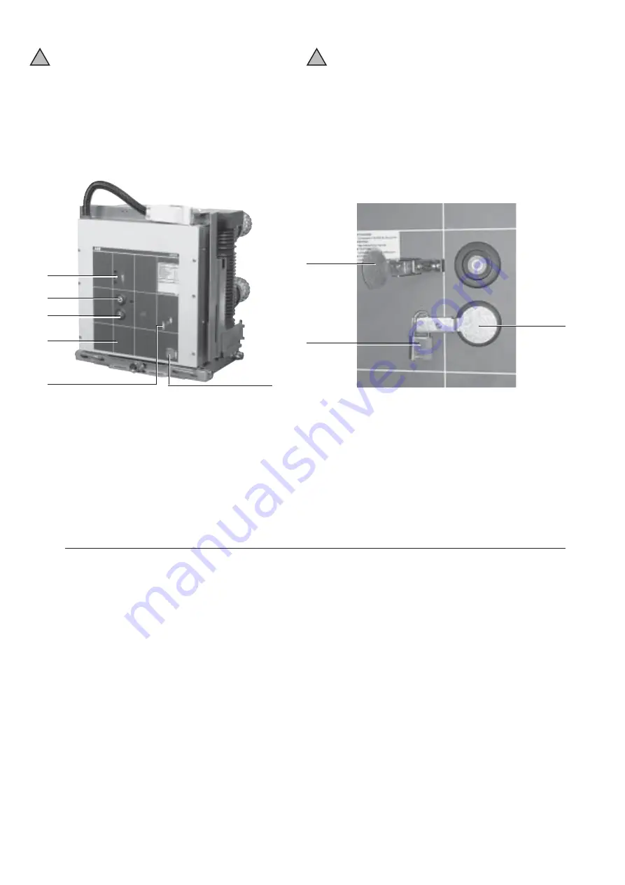
Legenda
1 Segnalatore stato della pressione SF6 (a richiesta)
2 Pulsante di apertura
3 Pulsante di chiusura
4 Segnalatore interruttore aperto/chiuso
5 Albero per la carica manuale delle molle di chiusura
6 Segnalatore molle di chiusura cariche/scariche
7 Blocco a luchetto della copertura del pulsante di chiusura
8 Copertura del pulsante di chiusura (blocco ad impedimento)
9 Blocco a lucchetto della copertura del pulsante di apertura
(a richiesta).
Fig. 50
6.4.2. Interruttore HD4
•
Qualora vengano effettuate manovre meccaniche
sugli interruttori al di fuori del quadro prestare la
massima attenzione alle parti in movimento.
•
Se le manovre risultassero impedite non forzare
gli interblocchi meccanici e verificare la correttez-
za della sequenza delle manovre.
•
L'inserimento e l'estrazione degli apparecchi nei
quadri deve essere graduale per evitare urti che
possono deformare gli interblocchi meccanici.
a) Manovra manuale di carica molle
Per caricare manualmente le molle di chiusura inserire a
fondo la leva di carica nella sede (5) e ruotare fino alla
comparsa del segnalatore (6) di colore giallo. Lo sforzo
normalmente applicabile alla leva di carica in dotazione è
160 N. In ogni caso lo sforzo massimo applicabile è 300 N.
b) Manovra elettrica di carica molle
A richiesta l’interruttore può essere dotato dei seguenti
accessori per la manovra elettrica:
– motoriduttore per la carica automatica delle molle di
chiusura;
– sganciatore di chiusura;
– sganciatore di apertura.
Il motoriduttore ricarica automaticamente le molle dopo
ogni operazione di chiusura fino alla comparsa del segna-
latore giallo (6). In caso di mancanza di tensione durante la
carica, il motoriduttore si ferma e riprende automaticamente
la ricarica delle molle al ritorno della tensione.
Caption
1 SF6 gas pressure indicator (on request)
2 Opening pushbutton
3 Closing pushbutton
4 Circuit-breaker open/closed indicator
5 Shaft for manual charging of the closing spring
6 Charged/discharged closing spring indicator
7 Padlock for closing pushbutton cover
8 Closing pushbutton cover (prevention lock)
9 Padlock of opening pushbutton cover (on request).
6.4.2. HD4 circuit-breaker
•
When performing mechanical operations on with-
drawn circuit-breakers pay the utmost attention to
the moving parts.
•
Should the operations be prevented, do not force
the mechanical interlocks but make sure that the
operating sequence is correct.
•
The apparatus racking in/out the switchboard must
be gradual so as to safeguard the mechanical
interlocks against any deforming impacts.
a) Manual spring charging
For manual closing spring charging, fully insert the charging
lever into the seat (5) and turn it until the yellow indicator (6)
appears. The normal force to be applied to the charging
lever is 160 N, the maximum force applicable is 300 N.
b) Electrical spring charging
On request, the circuit-breaker can be supplied with the
following accessories for electrical control:
– gear motor for automatic closing spring charging;
– shunt closing release;
– shunt opening release.
The gear motor automatically charges the springs after any
closing operation until the yellow indicator (6) appears.
Should the power fail while charging, the gear motor stops
and automatically restarts spring charging when the power
is restored.
!
!


