80/100 - 647647/001 - M3371 - 2000/08/30 it-en
1
2
9.8.2.2. Quadro non addossato alla parete (accessibilità
dal retro)
Prima di asportare il pannello posteriore accertar-
si di avere chiuso il sezionatore di terra e verificare
che il pannello sia quello dello scomparto su cui
si sta operando.
Collegamento dei cavi
– Svitare le viti di fissaggio dei pannelli e asportali;
– asportare le tracce di grasso con un panno pulito, asciutto ed
imbevuto di solvente prima dell’allacciamento delle connes-
sioni;
– asportare le lamiere di fondo dei cavi e forarle in corrispon-
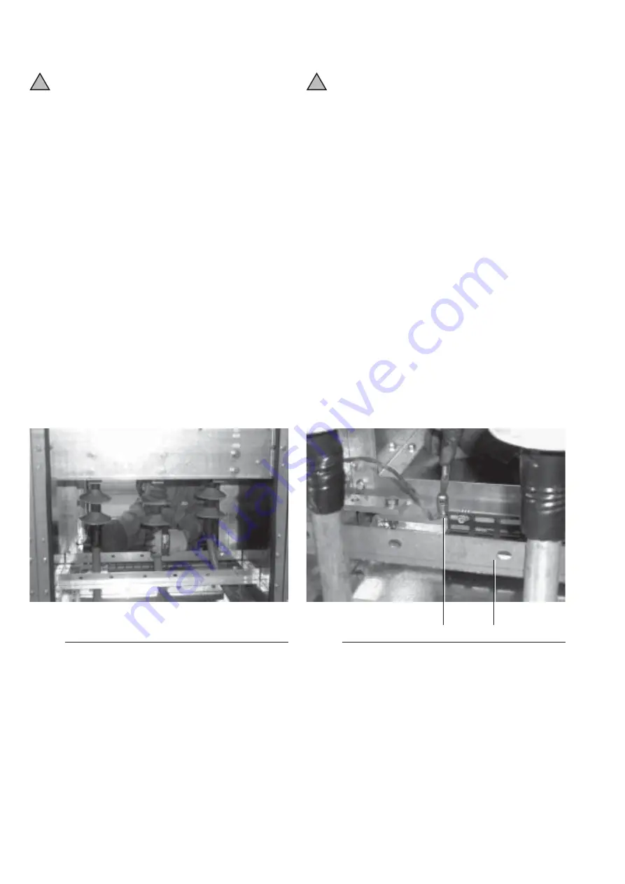
denza dell’ingresso dei cavi (1) (fig. 73 e 74), inserire il cavo
facendolo passare attraverso il trasformatore di corrente
toroidale eventualmente previsto;
– preparare la terminazione del cavo seguendo le istruzioni del
costruttore del cavo e dei terminali;
– connettere al quadro i capicorda (2) (fig. 73-74-76) dei
terminali dei cavi utilizzando apposite viti e rosette;
– collegare i capicorda degli schermi dei cavi (1) (fig. 77) alla
sbarra di terra del quadro usando le viti presenti;
– ancorare i cavi alla staffa di fissaggio (2) fig. 77;
– provvedere alla chiusura della feritoia di ingresso cavi;
– rimontare i pannelli asportati ed avvitare le viti di fissaggio.
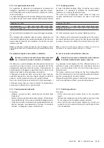
Fig. 76
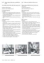
Fig. 77
9.8.2.2. Switchboard which cannot be placed against the
wall (access from the rear)
Before removing the rear panel, make sure that
the earthing switch is closed and the panel belongs
to the cubicle on which the operator is working.
Cable connection
– Unscrew the panel fixing screws and remove the panels;
– remove any grease by means of a clean, dry cloth soaked in
solvent before fastening the connections;
– remove the cable bottom sheets and drill them according to
the cable entries (1) (fig. 73-74), insert the cable making them
pass through the toroidal current transformer if supplied;
– set up the cable terminal following the instructions of the cable
and terminal manufacturer;
– connect the cable terminals to the switchboard (2) (fig. 73-74)
and (fig. 76) by means of the relevant screws and washers;
– connect the cable shield terminals (1) (fig. 77) to the switch-
board earthing busbar by means of the screws supplied;
– anchor the cables to the fixing bracket (2) (fig. 77);
– close the slot for the cable entry;
– remount the panels removed and fasten the fixing screws.
Access to the switchboard terminals from the VT com-
partment (wall-standing switchboard)
VT truck withdrawal
Follow the instructions in para. 6.2.
VT compartment dismantling
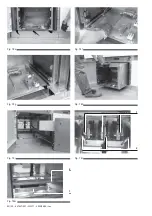
– Loosen the fixing screws (right and left side) of the VT
compartment (fig. 78 b-78c);
– move the guides (right and left) against the switchboard walls
(fig. 78d);
– loosen the panel fixing screws on the switchboard base (fig.
78e).
!
!
Accessibilità ai terminali del quadro dallo scomparto TV
(quadro addossato alla parete)
Estrazione del carrello TV
Seguire le istruzioni indicate al par. 6.2.
Smontaggio dello scomparto TV
– Svitare le viti di fissaggio (lato destro e sinistro) dello scom-
parto TV (fig. 78b - 78c);
– spostare le guide (destro e sinistro) contro le pareti del quadro
(fig. 78d);
– svitare le viti di fissaggio del pannello alla base del quadro
(fig. 78e);


