Universal Bypass Switch Unit
UNB
Operation Manual
UNB2357E / Page 23 (34)
8. Connections
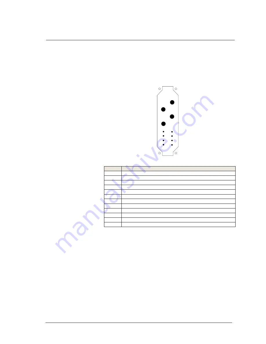
8.1 Pinning UNB 5.0, 12.5 kVA
connector X1 (HAN-K4/8, socket outlet):
1
3
2
4
5
6
7
8
9
10
11
12
Pin
Name
1
Source
1
(inverter)/Phase
L1
2
Source
2
(substitute
mains)/Phase
L1
3
Source
1
&
2/
neutral
4
UNB
Output/Phase
L1
5
DC
-
supply / L+ (24 / 48 / 108 / 216V DC)
6
DC-supply / L- (24 / 48 / 108 / 216V DC)
7
Synchronisation
/
SYNC
-
SIG
8
Synchronisation
/
SYNC
-
STAT
9
Indication
relay
general
fault
/
NC
10
Indication relay general fault / NO
11
Indication relay general fault / COM*
12
Synchronisation
/
SYNC
-
GND
*logic:fault = COM and NC closed
OK = COM and NO closed
In operation with an UNB it is necessary to connect
aditional toSYNC – GND, SYNC – SIG the contacts SYNC
– STAT between all of the inverters and the UNB.
Picture 8.1:
Pinning –
UNB 5.0kVA
UNB 12.5kVA


