19.1 Whole Unit Replacement
19.1.1 Versions with Removable Terminals
1.
Read all the warnings at the beginning of this section, refer to
SF910i Safety
Instruction Manual (EC-DOC-G041MAN033)
.
2.
Initially power-on the replacement unit on a work-bench in a safe area, and configure
its protocol (MODBUS) and its node address as the unit to be replaced. Refer to
communication network parameters.
3.
Turn-off the power supply.
4.
Wear the anti-static wrist strap or equivalent system.
5.
Loose the locking screw on the cover (requires an allen wrench).
6.
Unscrew the cover.
7.
Unplug all the removable connectors and “shield” terminal from the round board
after taking note of the assignment.
8.
Loose the cable gland and unscrew it from the enclosure.
9.
Carefully remove the cable harness from the enclosure.
10. Unscrew the whole enclosure from the mechanical adapter that holds it at the light
entrance port.
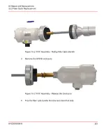
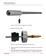
11. If an optical fiber is present, clean its cold terminal before proceeding.
12. Mount the new unit in place.
13. Insert the cable harness in the cable entry bore.
14. Re-install the cable gland.
15. Plug all the connectors and “shield” terminal in the respective sockets in the round
board.
16. Re-install the cover and tight the locking screw. Follow the requirement as in
SF910i
Safety Instruction Manual (EC-DOC-G041MAN033)
.
No tightening tool is required. Hand turning is recommended up to complete closure
(minimum 6 turns). Socket head screw must be tightened to prevent the lid from
loosen.
8VZZ005286 B
120
19 Repair and Replacement
19.1 Whole Unit Replacement
Summary of Contents for Uvisor SF910i
Page 2: ......
Page 6: ......
Page 20: ...8VZZ005286 B 20...
Page 30: ...8VZZ005286 B 30...
Page 68: ...8VZZ005286 B 68...
Page 78: ...8VZZ005286 B 78...
Page 90: ...8VZZ005286 B 90...
Page 92: ...8VZZ005286 B 92...
Page 98: ...8VZZ005286 B 98...
Page 108: ...8VZZ005286 B 108...
Page 114: ...8VZZ005286 B 114...
Page 118: ...8VZZ005286 B 118...
Page 126: ...8VZZ005286 B 126...
Page 128: ...8VZZ005286 B 128...
Page 130: ...8VZZ005286 B 130...
Page 150: ...8VZZ005286 B 150...
Page 151: ...Appendix E Drawings 8VZZ005286 B 151 E Drawings...
Page 152: ...Figure E 1 Enclosure Quick Release Connector and Version LOS 8VZZ005286 B 152 E Drawings...
Page 153: ...Figure E 2 Enclosure NPT Cable Inlet and Version LOS 8VZZ005286 B 153 E Drawings...
Page 154: ...Figure E 3 Enclosure Quick Release Connector and Version FOC 8VZZ005286 B 154 E Drawings...
Page 155: ...Figure E 4 Enclosure NPT Cable Inlet and Version FOC 8VZZ005286 B 155 E Drawings...
Page 156: ...Figure E 5 FOC Flexible Assembly 8VZZ005286 B 156 E Drawings...
Page 157: ...Figure E 6 FOC Rigid Assembly 8VZZ005286 B 157 E Drawings...
Page 160: ...Figure E 9 Bailey Flame ON Standard Replacement 8VZZ005286 B 160 E Drawings...
Page 161: ...Figure E 10 Typical Bailey Flame ON Installation 8VZZ005286 B 161 E Drawings...
Page 162: ...8VZZ005286 B 162...
Page 170: ...8VZZ005286 B 170...
Page 178: ...G 7 Counter Flange 8VZZ005286 B 178 G Fittings G 7 Counter Flange...
Page 189: ......

