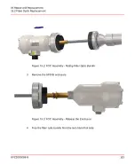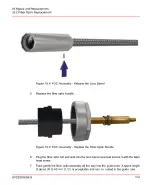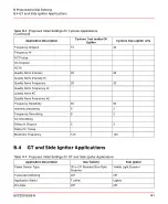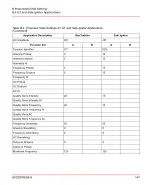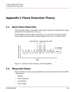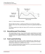
Appendix B Proposed Initial Setting
Notes on the Proposed Initial Settings
Important values for flame detection that must be set before initial start-up are shown in
bold.
Other values that can be changed, but are not critical for flame detection are shown in
plain text.
Using Flame Explorer tool, the user can load from a file the predefined and default
values for a wide range of standard applications. Refer to
SF910i Flame Explorer
User Manual (8VZZ005308)
for details, and for a list of the pre-defined configurations
that are available.
For safety reasons, the user is requested to prove the Flame Failure Response
Time (FFRT) of the SF910i under any burner load/fuel conditions and under any
selected file of parameters. For EN298 application, the user need to set the
DELAY
DROPOUT
parameter to <= 0.9s to fulfill the requirement of EN 298 that the FFRT
shall not exceed one second. If there are further adjustments of the flame detector
(DELAY DROPOUT), do not cause the time to rise above one second.
B.1
Corner Applications
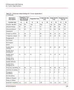
Table B.1: Proposed Initial Settings for Corner Applications
Tangential-Gas
and Oil
Tangential-Oil
only
Tangential-Gas
only
Tangential-Coal
Tangential-Coal
w/oil Warm-up
Discriminate
Application
Description
VL or UV Fibre
Optic Scanner
Visible Light
Fiber Optic
Scanner
UV Fiber Optic
Scanner
Visible Light
Fiber Optic
Scanner
Visible Light Fiber
Optic Scanner
Flame Sensor Type
On
On
Off
Off
On
Fuel/Load Switching
Corner
Corner
Corner
Corner
Corner
Application Select
Off
Off
Off
Off
Off
Hi Limits
Off
Off
Off
Off
Off
AC Amplitude
8VZZ005286 B
137
B Proposed Initial Setting
B.1 Corner Applications
Summary of Contents for Uvisor SF910i
Page 2: ......
Page 6: ......
Page 20: ...8VZZ005286 B 20...
Page 30: ...8VZZ005286 B 30...
Page 68: ...8VZZ005286 B 68...
Page 78: ...8VZZ005286 B 78...
Page 90: ...8VZZ005286 B 90...
Page 92: ...8VZZ005286 B 92...
Page 98: ...8VZZ005286 B 98...
Page 108: ...8VZZ005286 B 108...
Page 114: ...8VZZ005286 B 114...
Page 118: ...8VZZ005286 B 118...
Page 126: ...8VZZ005286 B 126...
Page 128: ...8VZZ005286 B 128...
Page 130: ...8VZZ005286 B 130...
Page 150: ...8VZZ005286 B 150...
Page 151: ...Appendix E Drawings 8VZZ005286 B 151 E Drawings...
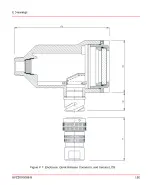
Page 152: ...Figure E 1 Enclosure Quick Release Connector and Version LOS 8VZZ005286 B 152 E Drawings...
Page 153: ...Figure E 2 Enclosure NPT Cable Inlet and Version LOS 8VZZ005286 B 153 E Drawings...
Page 154: ...Figure E 3 Enclosure Quick Release Connector and Version FOC 8VZZ005286 B 154 E Drawings...
Page 155: ...Figure E 4 Enclosure NPT Cable Inlet and Version FOC 8VZZ005286 B 155 E Drawings...
Page 156: ...Figure E 5 FOC Flexible Assembly 8VZZ005286 B 156 E Drawings...
Page 157: ...Figure E 6 FOC Rigid Assembly 8VZZ005286 B 157 E Drawings...
Page 160: ...Figure E 9 Bailey Flame ON Standard Replacement 8VZZ005286 B 160 E Drawings...
Page 161: ...Figure E 10 Typical Bailey Flame ON Installation 8VZZ005286 B 161 E Drawings...
Page 162: ...8VZZ005286 B 162...
Page 170: ...8VZZ005286 B 170...
Page 178: ...G 7 Counter Flange 8VZZ005286 B 178 G Fittings G 7 Counter Flange...
Page 189: ......

