Flame Relay
Flame-relay is an ON/OFF switch that is energized (i.e. contact is closed - ON) when a
flame is detected and de-energized (contact open - OFF) when a flame is not detected.
See
for more information about flame detection.
The user can configure the SF910i to perform flame detection based on the requirements.
Flame Failure Response Time (FFRT) is programmable from Delay Dropout 0.2 to 4s
in 0.1s increments, corresponding to acture FFRT time to be 0.3 – 4.2s. The difference
between setting Dropout and acture FFRT time is due to the additional relay/program
action delay.
For safety reasons, the user is requested to prove the FFRT of the SF910i under
any burner load/fuel conditions, and under any selected file of parameters. For
EN298 application, the user needs to set the
DELAY DROPOUT
parameter to <=
0.9s to fulfil the requirement of EN 298 that the FFRT shall not exceed one second.
If there is a further adjustments of the flame detector (DELAY DROPOUT), it do not
cause the time to rise above one second.
Safe Relay
Safe-relay is an ON/OFF switch that is energized (i.e. contact is closed - ON) when no
faults are present and de-energized (contact open - OFF) when a fault is detected. This
relay can be used in an alternative to its default function, to be a “second flame relay”
or a “flame quality relay”. See details in the next sections of this document.
For SIL2 safety, IEC 60730-1, CAN/CSA E60730-1, or EN298 application, Safe-relay
need to be set into “second flame relay” condition, and needs to be serially connected
with Flame-relay contacts by customer to fulfil safety redundancy output.
Both relays go to OFF (contact open, de-energized) state, if any fault is detected (safe
status).
2.2.4
4-20mA
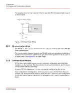
SF910i has a galvanic isolated 4-20mA analog output (external powered, see scheme
aside) that can be assigned to be proportional to one of the following flame variables:
–
Intensity
–
Flicker frequency
–
AC-amplitude
–
Quality
–
Flame temperature
8VZZ005286 B
36
2 Hardware
2.2 Display and Terminations Boards
Summary of Contents for Uvisor SF910i
Page 2: ......
Page 6: ......
Page 20: ...8VZZ005286 B 20...
Page 30: ...8VZZ005286 B 30...
Page 68: ...8VZZ005286 B 68...
Page 78: ...8VZZ005286 B 78...
Page 90: ...8VZZ005286 B 90...
Page 92: ...8VZZ005286 B 92...
Page 98: ...8VZZ005286 B 98...
Page 108: ...8VZZ005286 B 108...
Page 114: ...8VZZ005286 B 114...
Page 118: ...8VZZ005286 B 118...
Page 126: ...8VZZ005286 B 126...
Page 128: ...8VZZ005286 B 128...
Page 130: ...8VZZ005286 B 130...
Page 150: ...8VZZ005286 B 150...
Page 151: ...Appendix E Drawings 8VZZ005286 B 151 E Drawings...
Page 152: ...Figure E 1 Enclosure Quick Release Connector and Version LOS 8VZZ005286 B 152 E Drawings...
Page 153: ...Figure E 2 Enclosure NPT Cable Inlet and Version LOS 8VZZ005286 B 153 E Drawings...
Page 154: ...Figure E 3 Enclosure Quick Release Connector and Version FOC 8VZZ005286 B 154 E Drawings...
Page 155: ...Figure E 4 Enclosure NPT Cable Inlet and Version FOC 8VZZ005286 B 155 E Drawings...
Page 156: ...Figure E 5 FOC Flexible Assembly 8VZZ005286 B 156 E Drawings...
Page 157: ...Figure E 6 FOC Rigid Assembly 8VZZ005286 B 157 E Drawings...
Page 160: ...Figure E 9 Bailey Flame ON Standard Replacement 8VZZ005286 B 160 E Drawings...
Page 161: ...Figure E 10 Typical Bailey Flame ON Installation 8VZZ005286 B 161 E Drawings...
Page 162: ...8VZZ005286 B 162...
Page 170: ...8VZZ005286 B 170...
Page 178: ...G 7 Counter Flange 8VZZ005286 B 178 G Fittings G 7 Counter Flange...
Page 189: ......

