7.4
Tuning Display
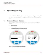
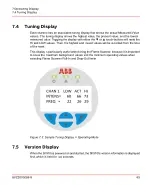
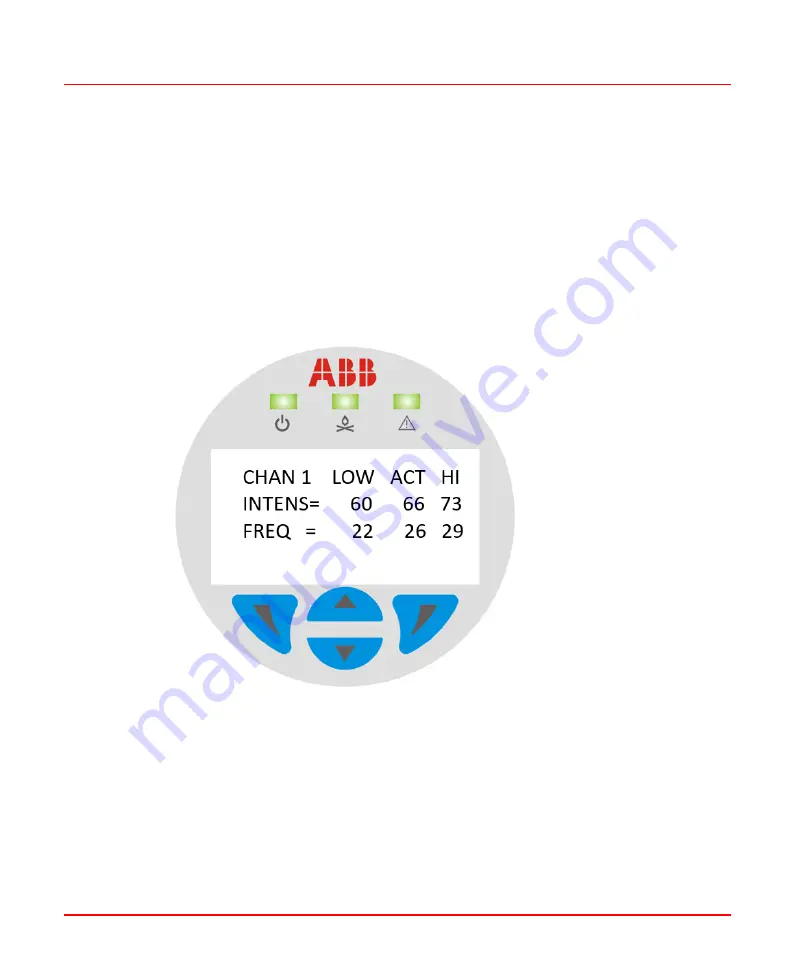
Each channel has an associated tuning display that shows the actual Measured-Value
values. The tuning display shows the highest value, the present value, and the lowest
measured value. Toggling the display with either the ▼ or ▲ touch-buttons will reset the
HI and LOW values. Then, the highest and lowest values will be recorded from the time
of the reset.
This display is particularly useful when tuning the Flame Scanner, because it is important
to know the maximum background values and the minimum operating values when
selecting Flame Scanner Pull-In and Drop-Out limits.
Figure 7.3: Sample Tuning Display in Operating-Mode
7.5
Version Display
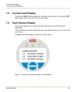
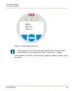
When the SF910i is powered on and started, the SF910i’s version information is displayed
first, which is held for two seconds.
8VZZ005286 B
65
7 Operating Display
7.4 Tuning Display
Summary of Contents for Uvisor SF910i
Page 2: ......
Page 6: ......
Page 20: ...8VZZ005286 B 20...
Page 30: ...8VZZ005286 B 30...
Page 68: ...8VZZ005286 B 68...
Page 78: ...8VZZ005286 B 78...
Page 90: ...8VZZ005286 B 90...
Page 92: ...8VZZ005286 B 92...
Page 98: ...8VZZ005286 B 98...
Page 108: ...8VZZ005286 B 108...
Page 114: ...8VZZ005286 B 114...
Page 118: ...8VZZ005286 B 118...
Page 126: ...8VZZ005286 B 126...
Page 128: ...8VZZ005286 B 128...
Page 130: ...8VZZ005286 B 130...
Page 150: ...8VZZ005286 B 150...
Page 151: ...Appendix E Drawings 8VZZ005286 B 151 E Drawings...
Page 152: ...Figure E 1 Enclosure Quick Release Connector and Version LOS 8VZZ005286 B 152 E Drawings...
Page 153: ...Figure E 2 Enclosure NPT Cable Inlet and Version LOS 8VZZ005286 B 153 E Drawings...
Page 154: ...Figure E 3 Enclosure Quick Release Connector and Version FOC 8VZZ005286 B 154 E Drawings...
Page 155: ...Figure E 4 Enclosure NPT Cable Inlet and Version FOC 8VZZ005286 B 155 E Drawings...
Page 156: ...Figure E 5 FOC Flexible Assembly 8VZZ005286 B 156 E Drawings...
Page 157: ...Figure E 6 FOC Rigid Assembly 8VZZ005286 B 157 E Drawings...
Page 160: ...Figure E 9 Bailey Flame ON Standard Replacement 8VZZ005286 B 160 E Drawings...
Page 161: ...Figure E 10 Typical Bailey Flame ON Installation 8VZZ005286 B 161 E Drawings...
Page 162: ...8VZZ005286 B 162...
Page 170: ...8VZZ005286 B 170...
Page 178: ...G 7 Counter Flange 8VZZ005286 B 178 G Fittings G 7 Counter Flange...
Page 189: ......

