19.1.2 Connector Versions
1.
Read all the warnings at the beginning of this section, refer to
SF910i Safety
Instruction Manual (EC-DOC-G041MAN033)
.
2.
If the unit to be replaced is connected to a data communication network, initially
power-on the replacement unit on a work-bench in a safe area, and configure its
protocol (MODBUS) and its node address as the unit to be replaced. Refer to
communication network parameters.
3.
Turn-off the power supply.
4.
Disconnect the quick release connector.
5.
Disconnect the earthling cable, and make sure not to lose the screw and washer.
6.
Unscrew the whole enclosure from the mechanical adapter that holds it at the light
entrance port.
7.
If an optical fiber is present, clean its cold terminal before proceeding.
8.
Mount the new unit in place.
9.
Re-connect the earthling cable with its screw and washer.
10. Reconnect the quick release connector.
11. Make a final check against the requirements of the
SF910i Safety Instruction Manual
(EC-DOC-G041MAN033)
.
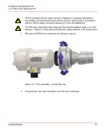
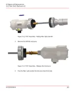
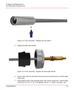
19.2 Fiber Optic Replacement
All repair/replacement operations must be executed by trained and authorized
personnel only.
Dangerous voltage (up to 50V
AC
) can be present on the relay terminals. Verify and
disconnect any dangerous voltage before proceeding.
The temperature of the hot terminal is 350°C or higher (662°F).
The unit under maintenance can be covered by ash and carbon particles.
Use protective clothing, gloves, and glasses.
8VZZ005286 B
121
19 Repair and Replacement
19.2 Fiber Optic Replacement
Summary of Contents for Uvisor SF910i
Page 2: ......
Page 6: ......
Page 20: ...8VZZ005286 B 20...
Page 30: ...8VZZ005286 B 30...
Page 68: ...8VZZ005286 B 68...
Page 78: ...8VZZ005286 B 78...
Page 90: ...8VZZ005286 B 90...
Page 92: ...8VZZ005286 B 92...
Page 98: ...8VZZ005286 B 98...
Page 108: ...8VZZ005286 B 108...
Page 114: ...8VZZ005286 B 114...
Page 118: ...8VZZ005286 B 118...
Page 126: ...8VZZ005286 B 126...
Page 128: ...8VZZ005286 B 128...
Page 130: ...8VZZ005286 B 130...
Page 150: ...8VZZ005286 B 150...
Page 151: ...Appendix E Drawings 8VZZ005286 B 151 E Drawings...
Page 152: ...Figure E 1 Enclosure Quick Release Connector and Version LOS 8VZZ005286 B 152 E Drawings...
Page 153: ...Figure E 2 Enclosure NPT Cable Inlet and Version LOS 8VZZ005286 B 153 E Drawings...
Page 154: ...Figure E 3 Enclosure Quick Release Connector and Version FOC 8VZZ005286 B 154 E Drawings...
Page 155: ...Figure E 4 Enclosure NPT Cable Inlet and Version FOC 8VZZ005286 B 155 E Drawings...
Page 156: ...Figure E 5 FOC Flexible Assembly 8VZZ005286 B 156 E Drawings...
Page 157: ...Figure E 6 FOC Rigid Assembly 8VZZ005286 B 157 E Drawings...
Page 160: ...Figure E 9 Bailey Flame ON Standard Replacement 8VZZ005286 B 160 E Drawings...
Page 161: ...Figure E 10 Typical Bailey Flame ON Installation 8VZZ005286 B 161 E Drawings...
Page 162: ...8VZZ005286 B 162...
Page 170: ...8VZZ005286 B 170...
Page 178: ...G 7 Counter Flange 8VZZ005286 B 178 G Fittings G 7 Counter Flange...
Page 189: ......

