Appendix D Glossary
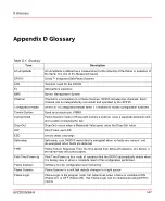
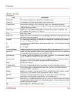
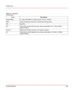
Table D.1: Glossary
Description
Term
AC-Amplitude is defined as a measurement of the intensity of the flicker or pulsation of
the flame. It is one of the Measured-Values
AC-Amplitude
Uvisor™ Integrated SafeFlame Scanner
SF910i
Terminal board for the SF910i
ATB
Atmosphere explosive
Ex
Burner Management System
BMS
Channel is a connection to a Flame Scanner. SF910i includes two channels. Each
channel can be independently connected and operated by the SF910i
Channel
SF910i is in Configuration-Mode when it is enabled to modify configuration functions
Configuration-Mode
Used as synonymous of BMS
Control System
Flame Scanner made of three parts namely a scanner head, a separate electronic unit,
and a cable connecting the two
Conventional
Drop-Out occurs when a Measured-Value goes below the Drop-Out value
Drop-Out
Direct View, see LOS
DW
Electro Static Discharge
ESD
Safe-relay is an ON/OFF switch that is energized when no faults are present, and
de-energized when faults are detected
Safe-relay
Flame Failure Response Time, the time period from flame-off (absence of a flame) to
the flame-relay off (contact open)
FFRT
First-Time Power up is a mode of operation that the SF910i automatically enters when
it is factory new or when a complete reset of the configuration performed
First-Time Power up
Software tool for configuration and monitoring
Flame Explorer
Flame Scanner is a unit that detects changes in a light source
Flame Scanner
Flame-Logic is the program code that determines when a flame is considered ON
(Flame-On) or OFF (Flame-Off). This Flame-Logic can be customized using SF910i
menus
Flame-Logic
8VZZ005286 B
147
D Glossary
Summary of Contents for Uvisor SF910i
Page 2: ......
Page 6: ......
Page 20: ...8VZZ005286 B 20...
Page 30: ...8VZZ005286 B 30...
Page 68: ...8VZZ005286 B 68...
Page 78: ...8VZZ005286 B 78...
Page 90: ...8VZZ005286 B 90...
Page 92: ...8VZZ005286 B 92...
Page 98: ...8VZZ005286 B 98...
Page 108: ...8VZZ005286 B 108...
Page 114: ...8VZZ005286 B 114...
Page 118: ...8VZZ005286 B 118...
Page 126: ...8VZZ005286 B 126...
Page 128: ...8VZZ005286 B 128...
Page 130: ...8VZZ005286 B 130...
Page 150: ...8VZZ005286 B 150...
Page 151: ...Appendix E Drawings 8VZZ005286 B 151 E Drawings...
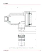
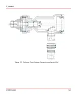
Page 152: ...Figure E 1 Enclosure Quick Release Connector and Version LOS 8VZZ005286 B 152 E Drawings...
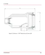
Page 153: ...Figure E 2 Enclosure NPT Cable Inlet and Version LOS 8VZZ005286 B 153 E Drawings...
Page 154: ...Figure E 3 Enclosure Quick Release Connector and Version FOC 8VZZ005286 B 154 E Drawings...
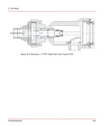
Page 155: ...Figure E 4 Enclosure NPT Cable Inlet and Version FOC 8VZZ005286 B 155 E Drawings...
Page 156: ...Figure E 5 FOC Flexible Assembly 8VZZ005286 B 156 E Drawings...
Page 157: ...Figure E 6 FOC Rigid Assembly 8VZZ005286 B 157 E Drawings...
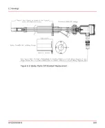
Page 160: ...Figure E 9 Bailey Flame ON Standard Replacement 8VZZ005286 B 160 E Drawings...
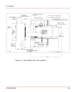
Page 161: ...Figure E 10 Typical Bailey Flame ON Installation 8VZZ005286 B 161 E Drawings...
Page 162: ...8VZZ005286 B 162...
Page 170: ...8VZZ005286 B 170...
Page 178: ...G 7 Counter Flange 8VZZ005286 B 178 G Fittings G 7 Counter Flange...
Page 189: ......


