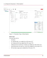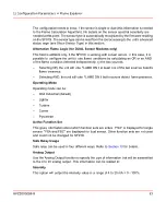
Channel Identifiers
–
Unit ID
–
Elevation ID
–
Burner/Combustor/Corner/Lighter ID
The term displayed by the menu will change with “Operation-Mode” selected.
8.3.4
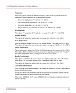
AO Output
Use the Analog Output function to specify the type of information that will be transmitted
to the 4 to 20 analog output. This information can be related to:
–
Intensity - This option will output the intensity value in a range of 4 to 20 mA = 0 -
100%.
–
Frequency - This option outputs the Flicker-Frequency value which is proportional
to the maximum Flicker-Frequency for the application selected.
•
For corner applications: 4 to 20 ma = 0 - 125 Hz
•
For wall/industrial applications: 4 to 20 ma = 0 - 125 Hz
•
For lighter applications: 4 to 20 ma = 0 - 125 Hz
•
For gas turbines: 4 to 20 ma = 0 -125 Hz or 0 - 250 Hz
–
AC-Amplitude - This option will output the AC-Amplitude in a range of 4 to 20 mA =
0 to 100%.
–
Quality (default) - This option will output the quality value in a range of 4 to 20 mA
= 0 to 100%.
8.3.5
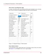
Load Default Parameters
From the local pushbuttons/display, it is possible to request to the unit to load back its
factory default parameters.
In this way, all the unit parameters will be brought back to the factory default with the
following exception, the active protocol will NOT change.
If the unit is MODBUS, it will remain MODBUS (but will bring back address and baud
rate to 1/38.400).
8.3.6
Communication
Use this function to enter the communication protocol type, addresses, and baud rates
for the serial outputs.
8VZZ005286 B
71
8 Configuration-Mode
8.3 Configuration Menu Descriptions
Summary of Contents for Uvisor SF910i
Page 2: ......
Page 6: ......
Page 20: ...8VZZ005286 B 20...
Page 30: ...8VZZ005286 B 30...
Page 68: ...8VZZ005286 B 68...
Page 78: ...8VZZ005286 B 78...
Page 90: ...8VZZ005286 B 90...
Page 92: ...8VZZ005286 B 92...
Page 98: ...8VZZ005286 B 98...
Page 108: ...8VZZ005286 B 108...
Page 114: ...8VZZ005286 B 114...
Page 118: ...8VZZ005286 B 118...
Page 126: ...8VZZ005286 B 126...
Page 128: ...8VZZ005286 B 128...
Page 130: ...8VZZ005286 B 130...
Page 150: ...8VZZ005286 B 150...
Page 151: ...Appendix E Drawings 8VZZ005286 B 151 E Drawings...
Page 152: ...Figure E 1 Enclosure Quick Release Connector and Version LOS 8VZZ005286 B 152 E Drawings...
Page 153: ...Figure E 2 Enclosure NPT Cable Inlet and Version LOS 8VZZ005286 B 153 E Drawings...
Page 154: ...Figure E 3 Enclosure Quick Release Connector and Version FOC 8VZZ005286 B 154 E Drawings...
Page 155: ...Figure E 4 Enclosure NPT Cable Inlet and Version FOC 8VZZ005286 B 155 E Drawings...
Page 156: ...Figure E 5 FOC Flexible Assembly 8VZZ005286 B 156 E Drawings...
Page 157: ...Figure E 6 FOC Rigid Assembly 8VZZ005286 B 157 E Drawings...
Page 160: ...Figure E 9 Bailey Flame ON Standard Replacement 8VZZ005286 B 160 E Drawings...
Page 161: ...Figure E 10 Typical Bailey Flame ON Installation 8VZZ005286 B 161 E Drawings...
Page 162: ...8VZZ005286 B 162...
Page 170: ...8VZZ005286 B 170...
Page 178: ...G 7 Counter Flange 8VZZ005286 B 178 G Fittings G 7 Counter Flange...
Page 189: ......

