background image

15 

1ZSE 5492-115 en, Rev. 5

3. Drying

Drying of the on-load tap-changer is normally not required, see section 2.2, step 6. 

The following temperatures and pressures between the on-load tap-changer tank and the 
transformer tank are allowed when drying:

Pressure

Standard on-load tap-changer

On-load tap-changer with reinforced 
barrier

Zero

Up to 115 °C (239 °F) on the 

transformer side.

Up to 90 °C (194 °F) inside the tank.

Up to 115 °C (239 °F) on the 

transformer side. 

Up to 90 °C (194 °F) inside the tank.

Up to 100 kPa

Up to 60 °C (140 °F).

Up to 90 °C (194 °F).

100–150 kPa

Not allowed.

Up to 60 °C (140 °F).

The temperature inside the motor drive cabinet must not exceed 70 °C (158 °F).
During or after drying the on-load tap-changer must not be operated until it has been filled 

with oil. The motor-drive mechanism should not be included in a vacuum process, as the 
process would remove the grease necessary for operation.

3  Drying 

Summary of Contents for UZE

Page 1: ...On load tap changers type UZE and UZF with motor drive mechanism type BUF 3 Installation and commissioning guide 1ZSE 5492 115 en Rev 5 ...

Page 2: ...This document must not be copied without our written permission and the contents thereof must not be imparted to a third party nor be used for any unauthorized purpose Contravention will be prosecuted ...

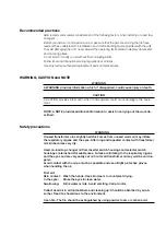
Page 3: ...ditional information to assist in carrying out the work de scribed Safety precautions WARNING Unused transformer oil is slightly harmful Fumes from unused warm oil may irritate the respiratory organs and the eyes After long and repeated contact with transformer oil skin becomes very dry Used on load tap changer oil from diverter switch housings and selector switch housings contains harmful substan...

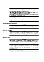
Page 4: ...ure and temperature at the rear during drying process see chapter 3 Mounting of gaskets CAUTION Sealing surfaces and gaskets must be clean and undamaged Diametrically opposed bolts in sealing joints must be tightened alternately several times beginning with a low tighten ing torque and finally with the recommended tightening torque as described in section 1 7 Tightening Torque in this guide During...

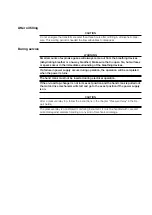
Page 5: ...ing devices If a failure in power supply occurs during operation the operation will be completed when the power returns The hand crank must not be inserted during electrical operation If the on load tap changer is not in its exact position and the hand crank is pulled out the motor drive mechanism will start and go to the exact position if the power supply is on CAUTION After a pressure relay trip...

Page 6: ......

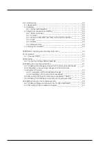
Page 7: ...of the regulating winding of the transformer_ _______________18 4 3 Connection to the oil conservator_ _________________________________20 5 Pressure relay______________________________________________________21 5 1 General________________________________________________________21 5 2 Installation______________________________________________________21 5 3 Checking when commissioning the transform...

Page 8: ..._______________30 A1 Introduction_______________________________________________________30 A1 1 Required tools_________________________________________________30 A2 Receiving_________________________________________________________31 A2 1 Temporary storage before assembly_______________________________31 A3 Welding and mounting instruction_____________________________________31 A3 1 Welding of the...

Page 9: ...er being delivered without a tank the transformer manufacturer will supply the tank Appendix A includes a welding and mounting instruction It is easy to access all parts of the on load tap changer for maintenance and repair After draining the oil you simply unbolt and open the front cover to access any part you may need to inspect or replace Lifting eye Connection to oil conservator On load tap ch...

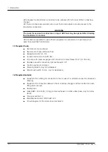
Page 10: ...renches Hexagonal wrench 8 mm Dynamometric wrench 5 85 Nm Air pump with pressure gauge and connection to male thread R 1 8 0 100 kPa Flexible tube with connection internal thread R 1 8 Tool for opening of oil drums Clamping blocks only for installation Small brush width 10 mm only for installation 1 2 Required material Equipment for oil filling for connection to the oil valve For dimensions see th...

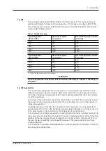
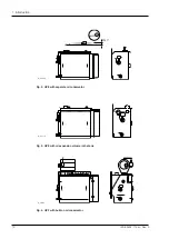
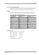
Page 11: ...ion volume in the tank ABB recommends the use of a separate conserva tor for the on load tap changer with both oil and air side separated from the main conserva tor of the transformer The volume of the conservator should be such that there is oil left in the conservator even at the lowest oil temperature expected and such that no flooding can occur at the highest oil temperature expected A suitabl...

Page 12: ...12 1ZSE 5492 115 en Rev 5 fm_00089 fm_00118 tc_00182 1 Introduction Fig 4 UZF with built on oil conservator Fig 3 UZE with oil expansion volume in the tank Fig 2 UZE with separate oil conservator Min 3 ...

Page 13: ...t of the motor drive mechanism is included in the overall weight Table 2 Weights for UZ on load tap changers in kg On load tap changer Type designation Tap changer with tank without oil Insert without motor drive mechanism UZE N UZE T 200 700 220 250 700 220 380 930 270 550 1100 340 650 1100 340 UZF N UZF T 200 720 220 250 720 220 380 900 270 550 1100 340 650 1100 340 The weight of the motor drive...

Page 14: ...er of the on load tap changer and send them to ABB for comments 4 Check that the quantity delivered the type designation and the serial number agree with the delivery documents e g the packing list or ABB s ordering acknowledgement The serial number is stamped on the rating plate 5 Remove the drying agent placed according to Fig 5 before the on load tap changer is taken into service 6 If the packi...

Page 15: ... 239 F on the transformer side Up to 90 C 194 F inside the tank Up to 115 C 239 F on the transformer side Up to 90 C 194 F inside the tank Up to 100 kPa Up to 60 C 140 F Up to 90 C 194 F 100 150 kPa Not allowed Up to 60 C 140 F The temperature inside the motor drive cabinet must not exceed 70 C 158 F During or after drying the on load tap changer must not be operated until it has been filled with ...

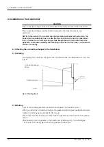
Page 16: ...g instruction In this case continue with section 4 2 directly 4 1 Attaching the on load tap changer to the transformer 4 1 1 Welding For welding the on load tap changer to the transformer tank use fillet weld with a 4 mm Fig 6 4 1 2 Bolting A set of cork rubber gaskets is provided to seal against the transformer tank When you install the on load tap changer the gasket should be glued as described ...

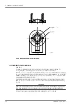
Page 17: ...s for a minimum of 3 hours Glue the inner gasket bands only both to the on load tap changer flange side and to the transformer tank flange side The required amount of glue ABB 1 3401 608 is 0 5 kg Do not glue gaskets at temperatures below 0 C 32 F NOTE ABB glue 1 3401 608 is a contact adhesive of nitrile rubber base May consist of two gaskets Supporting gasket Sealing gasket Corner gasket View A A...

Page 18: ...que should again be approximately 90 Nm Retighten the dome nuts with 42 Nm before oil filling See section 6 1 1 4 2 Connection of the regulating winding of the transformer On UZE the winding has to be connected from the rear On both UZE and UZF the cable lugs can be either crimped or brazed The free distance between the cable lugs for adjacent contacts must be at least 7 mm Tightening torque is 38...

Page 19: ...19 1ZSE 5492 115 en Rev 5 fm_000196 4 Installation on the transformer Fig 8 Assembly of the neutral connection Neutral connection ...

Page 20: ...ng that is left on the flange when the transport cover is removed After that the other bracket of the conservator is mounted to the tank For UZ with normal barrier the oil level difference between on load tap changer and trans former should be a maximum of 1 2 m For a reinforced barrier the oil level difference may be 8 m CAUTION Where the conservator is common to the transformer and the on load t...

Page 21: ...ation of the active part and repairing any faults may cause severe damage to the on load tap changer and the transformer The pressure relay can easily be tested by applying air pressure using a pump to the test tap on the valve The handle can be padlocked in the service position CAUTION The pressure relay is a calibrated monitoring instrument It must be handled with care and protected against care...

Page 22: ...ssure relay 3 Raise the pressure until the pressure relay trips the circuit breakers for the transformer 4 Read the pressure on the manometer and check against the pressure stated on the information plate Max permitted deviation is 10 5 Check that the alarm signal disappears when the pressure is lowered 6 After finishing the check turn the valve handle back to the service position Information plat...

Page 23: ...bout two weeks to let the gaskets settle at service temperature 6 2 Filling at atmospheric pressure 1 Open the conservator valve if any 2 Dismantle the pipe to the breather Or if simpler remove the air relief valve one way breather or the dehydrating breather 3 Connect the pump to the oil valve on the on load tap changer tank For dimension see the dimension drawing Open the valve and pump in oil t...

Page 24: ...and let air into the conservator or expansion volume 8 Reassemble the pipe or the breather The connections must be airtight therefore use sealing tape on the threads and O rings in the flanges 6 4 Correct oil level For installations where the on load tap changer and the transformer tank have a common oil conservator the instructions for the transformer should be used If possible the oil levels of ...

Page 25: ...hase sequence three phase supply is wrong the motor drive mechanism will start in LOWER direction The motor drive mechanism will stop when it has made approxi mately half of the complete operation and it will operate back and forth without the on load tap changer changing position until the control selector switch is turned to position 0 If the phase sequence is wrong reverse two of the motor supp...

Page 26: ...er all the gaskets have settled at service temperature The tightening torque for the gasket between the on load tap changer and the transformer is approximately 90 Nm The tightening torque for the front conver and the connection cover at UZF should be 42 Nm The welded stud bolts should not be overtightened 7 5 Resistance measurement If there are any problems with to high resistance during measurem...

Page 27: ...to obtain proper dehy dration 8 1 1 Transformer filled with oil Conservator mounted The on load tap changer should be filled with oil and connected to its conservator Conservator dismounted Drain about 20 of the oil from the on load tap changer Oil weights according to sec tion 1 3 Close the opening to the conservator with a transport cover UZE with oil expansion volume in the tank The on load tap...

Page 28: ...Motor protection The function of the protective motor switch should be checked For three phase AC motors remove one of the phase fuses and check the function time of the protective motor switch by a RAISE or LOWER operation The protective motor switch should release within 60 sec onds at a current setting equal to the rated current of the motor at the actual voltage If the protective motor switch ...

Page 29: ...ests Switch on the power afterwards Check that the air vents are open Remove the drying agent used during transport 9 3 6 Pressure relay Check the function as per section 5 3 9 4 Putting into operation Put the LOCAL REMOTE switch to REMOTE Reset the drag hands Make sure that no tools or foreign objects are left in the motor drive cabinet Close the door ...

Page 30: ... Chapter 4 in this appendix describes the case with inclined assem bly NOTE Most information on safety precautions and receiving and all information on drying oil filling and electrical connection and testing is to be found in the main docu ment A1 1 Required tools Welding equipment Lifting yoke Type designation Lifting yoke upright assembly Article No Lifting yoke inclined assembly Article No UZE...

Page 31: ...3 Welding and mounting instruction Weld the frame and flange to fit the motor drive mechanism BUF 3 Also fit an oil valve for filling and draining of the oil at the lowest possible position On top of the tank there should be a connection to a conservator and the conservator must have breathing device A3 1 Welding of the flange and frame for the motor drive mechanism Weld the flange to the end plat...

Page 32: ...mm LL 322 006 5 D 305 mm Assembly kit for flange 2 LL 322 005 A Type designation Dimensions mm A B C D E UZE 200 164 408 97 5 493 2 411 2 UZE 250 164 408 97 5 493 2 411 2 UZE 380 238 423 94 5 508 2 485 2 UZE 550 650 238 423 94 5 508 2 485 2 End plate 1 Welded Frame LL 322 007 F Flange 2 Tight welded 19 Bracket LL 114 006 7 230 2 Mounting bolts Hole in end plate 3 314 2 Welded Fig A2 Dimensions and...

Page 33: ...d tap changer Select a lifting yoke from the table in section A1 1 and fit it as shown in Fig A3 CAUTION The support according to Fig A3 must be attached before raising the on load tap changer to vertical position The link should not be attached Appendix A 3 Welding and mounting instruction Raise the on load tap changer to a vertical position by means of the lifting yoke and an overhead crane Atta...

Page 34: ... same time as shown in Fig A5 When the on load tap changer is fixed to the tank remove the lifting yoke and tighten the nuts by torque 42 Nm oil greased nuts M12 Remove the glass fibre stud used as trans port support Finally install the support for the geneva gear as shown in Fig A7 CAUTION The link according to Fig A4 must be attached before taking away the support View A A Link Fig A5 Shield ins...

Page 35: ... the driving disc of the motor drive mechanism see Fig A7 Secure the motor drive mechanism with four M12 nuts and spring washers When the on load tap changer and the motor drive mechanism are assembled remove the locking devices see Figs A7 and A8 WARNING The motor drive mechanism must be fitted in the slot on the lifting yoke during lifting Appendix A 3 Welding and mounting instruction CAUTION Th...

Page 36: ...pendix A 3 Welding and mounting instruction Support for geneva gear LL 114 007 F Driving disc Driving pin Fig A7 Positioning of driving pin Locking device Fig A8 Location of locking device Locking device in drive mechanism behind the control panel ...

Page 37: ...Washer Diagram pocket Screw M4x12 Nut M4 Spring washer Ordering No for the fittings above LL322 005 K Ordering No for the door painted with primer LL 322 007 B Rating plate Screw M3x5 Cover plate Gasket Nut M10 Screw M10 x 30 Filter Doorknob left or right Hinge right or left Screw washer M8x16 Gasket mounted on the edge of the frame Window glued to the door Screw M6x12 Spring washer Earth connecti...

Page 38: ... Weld the flange and install the pressure relay on the tank Appendix A 3 Welding and mounting instruction Flange LL 114 006 9 Hole in wall Ø 20 70 mm O ring Test tap Quickcoupling Three way valve Pressure relay LL 114 009 Stud M10x40 nut and washer Tight welded Fig A10 Attachment of pressure relay ...

Page 39: ...e and frame for motor drive mechanism Weld the flange to the end plate of the on load tap changer with dimensions A B C and tolerances as shown in Fig A12 and the A3 1 table Weld the frame to the end plate Finally weld the bracket to the end plate inside the tank Dimensions D and E and tolerances are also shown in Fig A12 and the A3 1 table Fig A12 Dimensions and weldings Welded Mounting bolts 230...

Page 40: ...le in section A1 1 which are mounted as shown in Fig A13 Strap the on load tap changer to the lifting yoke When the on load tap changer is raised remove the straps see Fig A14 and mount the on load tap changer to the tank as described in section A3 2 1 Appendix A 4 Welding instruction for inclined assembly Fig A13 Arrangement of lifting yoke Fig A14 Lifting after raising ...

Page 41: ......

Page 42: ......

Page 43: ......

Page 44: ...onents SE 771 80 Ludvika Sweden Phone 46 240 78 20 00 Fax 46 240 121 57 E Mail sales se abb com www abb com electricalcomponents Contact us Copyright 2010 ABB All rights reserved 1ZSE 5492 115 en Rev 5 2005 04 15 ...

Reviews: