39
1ZSE 5492-115 en, Rev. 5
A-A
A
A
1
B
A
Ø 6
3
D
C
E
fm_00084
Appendix A
4 Welding instruction for inclined assembly
A4 Welding instruction for inclined assembly
Carry out fitting of the on-load tap-changer in a tank with 30
o
inclination as described in
chapter A3, with the following exceptions.
A4.1 Welding of flange and frame for motor-drive mechanism
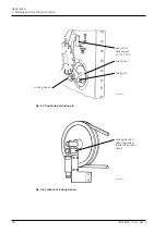
Weld the flange to the end plate of the on-load tap-changer with dimensions A, B, C and
tolerances as shown in Fig. A12 and the A3.1 table. Weld the frame to the end plate. Finally
weld the bracket to the end plate inside the tank.
Dimensions D and E and tolerances are also shown in Fig. A12 and the A3.1 table.
Fig. A12. Dimensions and weldings.
Welded
Mounting bolts
230±2
30
o
314±2
Frame
LL 322 007-F
Hole in end plate (3)
Bracket LL 114 006-7
19
End plate (1)
Welded
Flange (2)
Tight welded


