21
1ZSE 5492-128 en, Rev. 4
fm_00116
3 Repairs and adjustments
-
The glue is spread over the joint surfaces on the moulding. Then glue is spread over
the joint surfaces on the barrier. Thereafter glue is spread once more over the joint
surfaces on the moulding.
-
The glue is predried 10-30 minutes at 20 °C before the assembly. The glue should
be almost dry at assembly.
CAUTION
Assemble at room temperature. Glued details must not be moved or removed after assem
-
bling.
-
After predrying, mount the phase unit to the board. Use the distance pieces (see
step 12) to achieve the correct positioning of the phase unit.
-
Mount the clamps around the phase unit and brush the outer thread of the stud
bolts with polyvinylacetate glue.
-
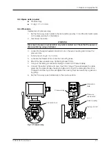
Mount the nuts on the studs and tighten them in the order shown in Fig. 6. Always
start with the middle of the three nuts for one clamp. Tighten with 5–15 Nm first and
thereafter twice with 22 Nm.
NOTE: Do not retighten the nuts.
14. Retighten all the nuts around the edge of the barrier board with a torque of 42 Nm.
15. Put the contact arms in the correct position and remount shafts (in the right position
and with the ends in the right position according to marking in point 5) with their cou
-
plings and shims, if any. Make sure that both of the outer screws in the couplings are
screwed in equally.
16. Check that the contact arms are in equal position and in the position indicated by the
motor-drive mechanism, see single-phase diagram. Check all plays shown in Fig. 7 and
adjust by adding or removing shims if necessary.
17. Place the gasket for the front cover on the studs of the flange (if loosened).
This gasket is not glued. The gasket surface against the cover is coated with grease to
facilitate openings in the future. Use grease as for ball-bearings.
3-phase unit
1-phase unit
Fig. 6. Mounting of gaskets.


