background image

Medium voltage products

V-Contact VSC 

Installation and service instructions

7.2/12 kV - 400 A

For your safety! 

1

I.  Introduction  

2

II.  Programme for environmental protection 

2

III. Application of the standards for X-ray emission 

3

IV. Safety information 

3

V.  Qualified personnel 

3

VI. Interventions in the field 

3

1.   Description 

4

  1.1.   “MAC” magnetic drive 

4

  1.2.   Versions available 

5

  1.3.   Characteristics 

6

  1.4.  Weights and overall dimensions 

6

  1.5. Performances 

8

  1.6.   Contactor auxiliary contacts 

8

  1.7. Compliance with Standards 

9

  1.8.   Protection against short-circuit  

9

2. Checking on receipt 

10

3. Handling 

11

  3.1.  Handling and lifting using a crane 

12

4. Storage 

13

5.   Installation 

14

  5.1.   General 

14

  5.2.  Installation and operating conditions 

14

  5.3.   Normal conditions 

14

  5.4.   Special conditions 

14

  5.5.   Overall dimensions 

15

  5.6.   Assembly and making the connections 

21

  5.7.   Description of the closing and opening operations   30
  5.8.  Manual emergency opening operation 

33

6.  Putting into service 

34

  6.1.   General procedures 

34

  6.2.   Racking the VSC/P


contactor in and out 

35

7.   Maintenance 

36

  7.1.   General 

36

  7.2.  Handling the MAC-R2 electronic card  

36

  7.3.   Inspection   

37

  7.4.   Servicing 

38

  7.5.   Servicing following a short-circuit or overload 

38

  7.6.   Repairs 

38

  7.7.   Instructions for dismantling or replacing fuses 

39

  7.8.   Replacement of the contactor fuses 

40

  7.9.   Mounting and dismantling the short-circuit busbar  43
  7.10. Putting the contactor back into service 

43


7.11. Checking the degree of vacuum of the interrupter 43

8.  Spare parts and accessories 

44

  8.1.  List of spare parts 

44

9. Product quality and environmental protection 

44

This instruction booklet refers to the following models:

VSC/F-VSC/FN-VSC/P-VSC/PG-VSC/PN-VSC/PNG

VSC-S/F-VSC-S/G-VSC-S/PG-VSC-S/PNG

NEPSI.COM - Northeast Power Systems. Inc.

Summary of Contents for V-Contact VSC 12/F

Page 1: ...5 Overall dimensions 15 5 6 Assembly and making the connections 21 5 7 Description of the closing and opening operations 30 5 8 Manual emergency opening operation 33 6 Putting into service 34 6 1 General procedures 34 6 2 Racking the VSC P contactor in and out 35 7 Maintenance 36 7 1 General 36 7 2 Handling the MAC R2 electronic card 36 7 3 Inspection 37 7 4 Servicing 38 7 5 Servicing following a ...

Page 2: ...NEPSI COM Northeast Power Systems Inc ...

Page 3: ...rding to the rules of good working practice and safety in the work place are constructed Strictly follow the information given in this instruction manual Check that the rated performance of the apparatus is not exceeded during service Check that the personnel operating the apparatus have this instruction manual to hand as well as the necessary information for correct intervention Pay special atten...

Page 4: ... at all times for revision and reference These instructions do not intend to cover all the details configurations or variants of the apparatus storage or installation For this reason the information given below may sometimes not contain the instructions regarding special configurations This does not relieve the user from their responsibility for using good technical working practices in applicatio...

Page 5: ...for correct intervention Strictly follow the information given in this instruction manual Make sure that during the installation service and maintenance stages the standard and legal requirements for constructing the installations in accordance with the regulations for safety in the workplace are respected Check that the rated performance of the apparatus is not exceeded during service V Qualified...

Page 6: ...opening coil supplied Fig C Magnetic circuit in the open position 1 1 MAC magnetic drive Based on the experience gained in the field of circuit breakers with magnetic drive ABB has implemented this technology in the field of contactors The magnetic drive adapts perfectly to this type of apparatus thanks to its precise and linear travel This means that a simple and direct axial transmission of the ...

Page 7: ...dy and will only close after self diagnosis has terminated ready state Careful selection of the components and a precise design make the electronic multi voltage feeder extremely reliable unaffected by electromagnetic interference generated by the surrounding environment and free of any emissions which may affect other apparatus placed in the vicinity These characteristics have made it possible fo...

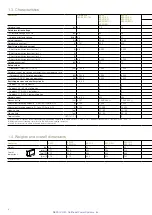
Page 8: ...es Operations hour SCO DCO Nr 4 102 4 1 200 1 200 Rated voltage of the voltage characteristics in category of use Category AC4 100 closing operations kA 6 102 4 4 000 4 000 Category AC4 25 opening operations kA 6 102 5 4 000 4 000 Switching devices and auxiliary circuits 4 8 4 9 Feeder 1 24 60 V dc basic Feeder 2 24 60 V dc full option Feeder 3 110 250 V dc ac basic Feeder 4 110 250 V dc ac full o...

Page 9: ... 1 VSC S PNG 1 GB T 14808 2001 DL T 593 2006 4 1 7 2 12 12 6 2 32 42 28 3 6 2 60 75 75 4 3 50 60 50 60 50 60 4 101 400 400 250 6 000 600 6 6 4 000 4 000 4 000 4 000 6 6 2 500 2 500 2 500 6 6 15 15 15 4 102 2 1 200 1 200 1 200 6 102 4 4 000 4 000 6 102 5 4 000 4 000 4 8 4 9 6 4 6 5 400 400 400 6 101 1 000 000 2 1 000 000 2 200 000 6 104 5 000 5 000 6 104 13 000 13 000 35 60 35 60 35 60 60 90 60 90 ...

Page 10: ...0 W Breaking capacity single contact τ 20 ms 110 V dc 440 W Breaking capacity two contacts in series τ 20 ms 250 V dc 440 W 1 5 Performances Contactor VSC7 VSC7 F VSC7 P VSC7 PN VSC7 PNG VSC7 FN VSC12 VSC12 F VSC12 P VSC12 PN VSC12 PNG Rated voltage kV 2 2 2 5 3 6 3 6 7 2 6 2 7 2 12 Ultimate performances for Motors kW 1 000 1 500 1 500 3 000 5 000 Transformers kVA 1 100 1 000 2 000 4 000 5 000 Cap...

Page 11: ...VA on resistive load Maximum breaking voltage 277 V AC 30 V DC Maximum breaking current 3 A Rated current 5 A 4 s Contact characteristics Maximum resistance with contact open 150 mohm measure of voltage drop 6 V DC 1 Maximum capacity 1 5 pF Trip times During closing 5 0 ms During release 2 0 ms Insulation Between contacts and coil 3000 V rms 50 Hz 1 min Between open contacts 750 V rms 50 Hz 1 min ...

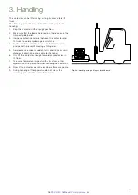
Page 12: ...ntactor avoiding any stress to the functional insulating parts and the terminals of the apparatus use the special lifting plates for the withdrawable version check the rating plate characteristics to make sure that the performances are suitable for the destined application and that they are those indicated in the order confirmation Should any damage or irregularity be noted in the supply on unpack...

Page 13: ... truck or onto the transport plate pallet to prevent it moving or tilting over 5 Avoid excessive speed sudden starts and stops or sharp changes in direction during contactor handling 6 Only lift the contactor enough to avoid any obstacles on the floor 7 Take care to avoid any impacts with structures other apparatus or with personnel when handling the contactor 8 Never lift a contactor over an area...

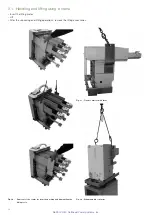
Page 14: ...es Lift After the unpacking and lifting operations remove the lifting accessories Fig 3c Fixed contactor with fuses Fig 3d Withdrawable contactor Fig 3b Removal of the contactor from the packing and dismantling the lifting tools NEPSI COM Northeast Power Systems Inc ...

Page 15: ...ide the packing with at least one standard packet per piece of apparatus Replace the packets approximately every 6 months Should the original packing no longer be available and immediate installation is not possible store in a covered well ventilated dry dust free non corrosive ambient with a dry atmosphere away from any flammable materials and at a temperature between 5 C and 40 C In any case avo...

Page 16: ... 1 General Correct installation is of primary importance The manufacturer s instructions must be carefully studied and followed It is good practice to use gloves for handling the pieces during installation The areas involved in the passage of power conductors or conductors of auxiliary circuits must be protected against access of any animals which might cause damage or disservices The contactor en...

Page 17: ...two shown in figure 4b Fig 4a 1 The width of the contactor varies based on the presence of the interfacing shafts 2 Hole for earthing the contactor 3 The maximum torque which can be applied to the interfacing shafts right and left is 2 Nm The rotation angle is approximately 10 1 The width of the contactor varies based on the presence of the interfacing shafts 2 Hole for earthing the contactor 3 Th...

Page 18: ...om figure 5c Installation of fixed contactors The performance of the contactor remains unaltered in the installation positions indicated below VSC 7 VSC 12 A Floor mounted with moving contacts at the bottom B Wall mounted with horizontal moving contacts and terminals at the bottom C Wall mounted with horizontal moving contacts and terminals at the top D Wall mounted with horizontal moving contacts...

Page 19: ...15 623 10 12 12 11 28 VSC7 FN 1 The width of the contactor varies according to the presence of the interfacing shafts 2 Hole for grounding the contactor 3 The maximum torque which can be applied to the interfacing shafts right and left is 2 Nm The rotation angle is about 10 Fig 5a Fig 5b NEPSI COM Northeast Power Systems Inc ...

Page 20: ...erfacing shafts 2 Hole for grounding the contactor 3 The maximum torque which can be applied to the interfacing shafts right and left is 2 Nm The rotation angle is about 10 Fig 5c Fig 5d Installation of the fixed contactor with VSC F VSC FN fuses NEPSI COM Northeast Power Systems Inc ...

Page 21: ... 8 10 115 115 491 5 46 310 15 339 350 653 5 19 129 8 616 16 5 10 1 2 16 8 5 376 50 1 2 19 4 8 57 55 5 30 5 OUT TEST IN 208 45 80 1 2 10 VSC7 P VSC7 PG VSC12 P VSC12 PG 5 5 3 Withdrawable contactor with VSC P VSC PG VSC PN VSC PNG fuses Fig 6a Fig 6b NEPSI COM Northeast Power Systems Inc ...

Page 22: ... 5 1 2 19 4 8 57 55 5 30 5 OUT TEST IN 208 45 80 1 2 1 2 19 530 14 503 103 4 433 4 600 657 19 5 412 205 1 629 642 596 25 5 35 264 1 503 150 150 9 620 30 187 458 0 5 42 8 453 0 5 0 340 Fig 6c Type Fuse A B VSC 12 PN Single 108 269 5 VSC 7 PNG Double 129 270 5 VSC 12 PNG Double 108 269 5 Fig 6d VSC 12 P contactor for marine environments NEPSI COM Northeast Power Systems Inc ...

Page 23: ...ickness Assembly procedures for fixed contactors Check that the contact surfaces of the connections are flat and are free of any burrs traces of oxidation or deformation caused by drilling or impacts received Carry out the operations indicated on the contact surface of the conductor silver plated copper clean with a rough dry cloth only in the case of obstinate traces of oxidation clean with a ver...

Page 24: ...nd of the minimum length needed Connection of metallic structures to exposed conductive parts In the case of painted parts of the supporting structure the various parts must always be scraped to eliminate the paint and connected with busbars or copper braids so as to guarantee low inductance connections To make a low inductance earthing connection use cables or busbars with an appropriate cross se...

Page 25: ...ed out correctly Figs 8c 8d show a grounding operation not carried out correctly and which apart from being dangerous does not guarantee correct operation of the VSC Where possible the power supply and auxiliary circuit cables must be braided Their length must be calculated appropriately to prevent any surplus and the maximum length must be 135 m for 24 to 130 V auxiliary voltage 400 m for 220 to ...

Page 26: ...ary input n 3 SFL2 Undervoltage pole 1 Undervoltage pole 1 XDB10 12 Binary input n 3 Undervoltage pole 2 Undervoltage pole 2 For availability ask ABB Connection of the auxiliary circuits The cables to be used for connection of the auxiliary circuits must have a rated voltage Uo U of 450 750 V and be insulated for 3 kV test Note before carrying out the test disconnect the earthing connection of the...

Page 27: ...mer the enclosures build up medium voltage switchgear consisting of various units Rules for designing the switchgear Arc proofing The ABB enclosures are supplied with a reinforced door suitable for making arc proof switchgear The reinforced enclosure alone cannot guarantee arc proofing of the switchgear designed by the customer To guarantee this some representative configurations selected by the c...

Page 28: ...upports closed at the front by the protection with characteristics nameplate In the top part of the protection there are strikers 30a and 30b fig 11 for actuating the enclosure contacts to signal the connected isolated position The pin 34 for locking contactor racking in with the earthing switch closed on the enclosure comes out on the right side of the truck The crosspiece for hooking up the cont...

Page 29: ... a contactor into service in an enclosure preset for a circuit breaker Fig 11a Fig 11b Locking devices on the racking out truck Locking electromagnet on the contactor truck which when there is no voltage prevents racking in or racking out RL2 Mechanical lock which prevents contactor racking in if the enclosure door is not closed requires the same interlock in the fixed part 108 Mechanical interloc...

Page 30: ...osed feeder able to operate in d c and a c a truck on which the base plate of the contactor is fixed and the front protective screen by means of two supports At the rear two pins are positioned on the side walls of the truck for locking contactor racking in with the earthing switch open on the enclosure whereas the 45 slides operate the segregation shutters of the medium voltage fixed contacts of ...

Page 31: ...29 RLE2 BGT3 1 3 2 4 5 12 1b 121 122 122 120 1c 126 125 1a Fig 12 Fig 12a Locking devices on withdrawable truck Fig 12b Interlocking devices on withdrawable truck NEPSI COM Northeast Power Systems Inc ...

Page 32: ...1 The contactor is restarted if the supply voltage of the board drops below 18V for more than 300ms 2 The undervoltage with time delay function is guaranteed with 18V minimum residual voltage TABLE 2a SCO Single Command Operated version Terminals XDB10 1 and XDB10 2 must always be supplied at the rated voltage tolerance 85 110 Closing operation Power supply in continuous mode to the UV input Openi...

Page 33: ... the opening and closing operations The table below indicates the functions available 5 7 3 Coil continuity control CCC and temperature monitoring The unit checks actuator connection continuity so as to reduce the risk of failure to operate following disconnection It also monitors the temperature of the board to reduce the risk of operating beyond the board s design limits This function is provide...

Page 34: ...d for all the direct and alternating current voltages within the reference range To change the voltage value defined during the ordering stage proceed as follows 1 remove the rear plastic protection fig 13a 2 access the MAC R2 electronic card fig 13b 3 prepare the dip switches according to the indications given on the last page of the electric circuit diagram After having set the desired value the...

Page 35: ...ective shield of the stored energy capacitor and not to touch the capacitor itself in any way 5 8 Emergency opening operation The contactor is fitted with manual emergency operation which must be carried out by suitably qualified personnel with in depth knowledge of the apparatus The following Standards must be taken into particular consideration during installation and service IEC 62271 1 DIN VDE...

Page 36: ...doubt carry out the check indicated in paragraph 7 3 Table 4 make sure that all the barriers and protective shields are correctly installed carry out the inspections indicated in table 3 On completion of the operations indicated check that everything is put back in its original position The check can only be considered as passed if all the tests indicated have had a positive outcome In the case of...

Page 37: ...tion of the truck motor rotor which behaving like a generator can cause reversal of voltage at the connection terminals This can damage the permanent magnet of the motor therefore all the truck racking in and racking out operations carried out with the manual lever must be done with the motor circuit de energized 6 2 1 Contactor with manual truck For the racking in and racking out operations of th...

Page 38: ...hat of the work surface earthed with an equipotential connection to the main grounding branch point It is advisable for the operator to wear conductive shoes and overalls and to wear earthed conductive arm bands Fig 13a 13b shows a maintenance kit consisting of an arm band and ground connection both fitted with a 1 MW integrated resistance Using suitable protective means to protect the electronic ...

Page 39: ...racks replace traces of surface discharges or damage In case of accidental impacts Carry out a voltage test with the contacts open at 15 kV 50 Hz for one minute If there is a discharge during the test the interrupter must be replaced because this type of phenomenon corresponds to deterioration in the degree of vacuum In case of need contact ABB Service 4 Interrupter contacts 1 year or 50 000 inter...

Page 40: ...nductors Replace the damaged parts which show discolouration melting or damage caused by electric arcs Pay special attention to the moving parts Carry out the Checking procedures indicated in par 6 of this manual before putting the apparatus back into service 7 6 Repairs Replacement with spare parts and accessories must only be carried out by ABB personnel or by suitably qualified personnel with a...

Page 41: ... 282 1 1974 Standards The fuseholder is always fitted with an automatic opening device for a fuse blowing This device prevents contactor closing when even a single fuse is missing 7 7 2 Preliminary operations for fuse replacement a VSC P The contactor must be racked out of the enclosure for replacement of the fuses The instructions for the racking out operations are given in the switchgear enclosu...

Page 42: ... adapter packing b Dismantling the fuses fig 19b Open the locking rings 49 fig 19b moving them in the direction shown by the arrows using the tool 50 and remove the fuse using the special tool 50 c Mounting the fuses fig 19c Open the locking rings 49 moving them in the direction shown by the arrows using the tool 50 fig 19b fully insert the fuses with the contacts fitted with striker on the opposi...

Page 43: ...41 49 50 50 49 Fig 19c Fig 19b NEPSI COM Northeast Power Systems Inc ...

Page 44: ...as shown in the drawing b Mounting the fuses fig 20b Mount the fuses or the adapter preassembled as indicated in par a with the striker indicated by the arrow facing the opposite side to the one of the contactor tulips and fix them by means of the screws 56 and the spring washers 57 c Dismantling the fuses To dismantle the fuses and relative adapters proceed in reverse order to par b and a d Assem...

Page 45: ...owing VIDAR tester test values Contactor rated voltage DC test voltage 7 2 kV 16 kV 12 kV 22 5 kV The test must always be carried out with the contactor open with the contacts at the nominal distance Procedure for testing the vacuum of the interrupter of the contactor poles turn off the power and make the working area safe according to the safety regulations of the IEC DIN VDE standards open the c...

Page 46: ...roduced in compliance with the requirements of the international standards regarding quality and environmental management systems In these fields the excellent level is proved by availability of the ISO 9001 and ISO 14001 certificates End of product life ABB is committed to respecting the requirements and laws for protection of the environment laid down according to the ISO 14001 Standard ABB offe...

Page 47: ...45 NEPSI COM Northeast Power Systems Inc ...

Page 48: ...berhausener Strasse 33 D 40472 Ratingen Phone 49 0 2102 12 1230 Fax 49 0 2102 12 1916 E mail calor info de abb com www abb com The data and illustrations are not binding We reserve the right to make changes without notice in the course of technical development of the product Copyright 2014 ABB All rights reserved 1VCD600943 V5207 Rev B en Instruction Manual 2014 06 V Contact VSC F P PN PNG gs NEPS...

Reviews: