8
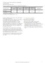
1.6. Contactor auxiliary circuits
10 auxiliary contacts (5 normally open and 5 normally closed)
are available on the contactor for the customer’s use, with the
following characteristics.
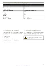
Auxiliary contacts characteristics
Rated voltage
24 … 660
V
Rated normal current
10
A
Rated short time current (30 ms, 20 times)
100
A
Rated frequency (for AC only)
50
Hz
Rated insulation voltage (DC)
800
V
Rated insulation voltage (AC)
660
V
Insulation test voltage
2500
V
Number of contacts
5
-
Stroke
6 … 7
mm
Maximum contact resistance
10
m
Ω
Storage temperature range
-20 … +120 °C
Operating temperature range
-20 … +70
°C
Emperature rise of contacts
30
K
Breaking capacity
(single contact
τ
= 20 ms, 250 V dc)
250
W
Breaking capacity
(single contact
τ
= 20 ms, 110 V dc)
440
W
Breaking capacity
(two contacts in series
τ
= 20 ms, 250 V dc)
440
W
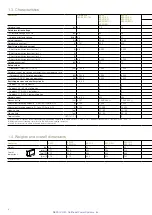
1.5. Performances
Contactor
VSC7
VSC7/F
VSC7/P
VSC7/PN
VSC7/PNG
VSC7/FN
VSC12
VSC12/F
VSC12/P
VSC12/PN
VSC12/PNG
Rated voltage
[kV] 2.2/2.5
3.6
3.6/7.2
6.2/7.2
12
Ultimate performances for:
Motors
[kW]
1,000
1,500
1,500
3,000
5,000
Transformers
[kVA]
1,100
1,000
2,000
4,000
5,000
Capacitors
[kVAR]
1,000
1,500
1,500
3,000
4,800 (
1
)
Contactor
VSC-S/G
VSC-S/F
VSC-S/PG
VSC-S/PNG
Rated voltage
[kV] 2.2/2.5
3.6
3.6/7.2
6.2/7.2
12
Ultimate performances for back-to-back capacitors banks
Rated current
[A] 250
250
250
250
250
Max. transient current of the capacitor
[kA] 8
8
8
8
8
Max. transient frequency of the capacitor
[kHz] 2.5
2.5
2.5
2.5
2.5
(1) Overvoltage surge arresters are compulsory between phases and between phase and earth.
NEPSI.COM - Northeast Power Systems. Inc.

