16
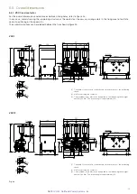
VSC 7 - VSC 12
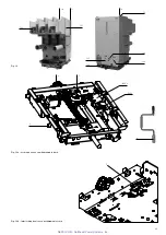
E
B
A
C
D
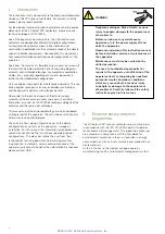
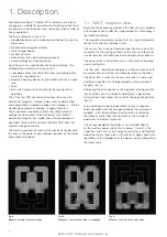
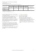
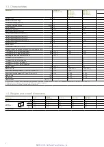
Fig. 4b
5.5.2. VSC/F contactor in fixed version with fuses
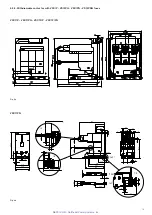
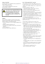
Please refer to figures 5a - 5b for the overall dimensions and the distances between the fixing holes.
In any case, avoid stressing the supporting structure of the contactor: if necessary, prepare slots in the fixing area to facilitate
correct positioning of the apparatus.
The contactor must be installed on the floor with moving contacts at the bottom (figure 5c).
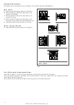
Installation of fixed contactors
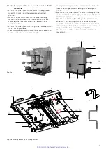
The performance of the contactor remains unaltered in the installation positions indicated below:
VSC 7 - VSC 12
A) Floor-mounted with moving contacts at the bottom.
B) Wall-mounted with horizontal moving contacts and
terminals at the bottom.
C) Wall-mounted with horizontal moving contacts and
terminals at the top.
D) Wall-mounted with horizontal moving contacts with
interrupters on the front (or rear) with vertical terminals.
E) Ceiling-mounted with moving contacts at the top.
VSC 7/F - VSC 12/F - VSC 7/FN
A) Floor-mounted with moving contacts at the bottom.
NEPSI.COM - Northeast Power Systems. Inc.

