5
The auxiliary power supply only has the aim of keeping the
capacitor charged.
Consumption is therefore minimal.
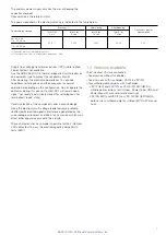
The power required by the electronic device is indicated in the table below:
Power supply voltage
Starting (
1
)
After closing
After opening
Continuous power
consumption
Inrush for
2 ms
Inrush for
6 sec
Inrush for
1.2 sec
Inrush for
1.2 sec
24...60 V cc
110...250 V cc
42 A (
2
)
35 W
25 W
30 W
5 W
110...250 V ac
Supply from voltage transformer or from UPS (Uninterrupted
Power System) not available.
Use the ABB S282UC-C3 thermal-magnetic circuit-breaker or
an equivalent type to protect the secondary circuits.
After powering, the electronic board takes 15 seconds
to perform self-diagnosis and then prepares for normal
operation, depending on the configuration. Do not operate the
contactor during this phase. Contact DO1 will remain open,
signal “not ready” and will only close after self-diagnosis has
terminated (“ready” state).
Careful selection of the components and a precise design
make the electronic multi-voltage feeder extremely reliable,
unaffected by electromagnetic interference generated by the
surrounding environment and free of any emissions which may
affect other apparatus placed in the vicinity.
These characteristics have made it possible for the V-Contact
VSC contactors to pass the electromagnetic compatibility
tests (EMC).
1.2. Versions available
The V-Contact VSC are available in:
– fixed version without fuseholder
– fixed versions with fuseholder: VSC/F e VSC/FN.
– four withdrawable versions with fuseholder:
- VSC/P (IEC) and VSC/PG or VSC-S/PG (IEC/GB-DL)
withdrawable versions for UniGear, PowerCube, CBE and
PowerBloc with manual or motorized truck
- VSC/PN (IEC) and VSC/PG or VSC-S/PNG (IEC/GB-DL)
both versions withdrawable for UniGear MCC with manual
truck.
(1) This value refers to a discharged capacitor.
(2) The value drops to 8 A for voltage values between 24...30V
NEPSI.COM - Northeast Power Systems. Inc.

