31
70-71
14
1
69
2
7.6. Instructions for dismantling and re-
placing fuses
7.6.1. General
All the operations described below
must be carried out by suitably
qualified personnel with in-depth
knowledge of the apparatus.
Do not rack the contactor out unless
the enclosure is securely fixed in the
switchgear or to a stable base.
Check that the contactor is open be-
fore proceeding with isolation and
its racking-out from the enclosure.
Check that the contactor is open be-
fore proceeding with replacement of
the fuses.
The withdrawable contactor is not
preset for housing fuses of CMF/BS
and CEF/BS type.
The fuseholder is preset for installation of fuses
with the dimensions and average type of striker
according to DIN 43625 (1983) and BS 2692
(1975) Standards and with electrical charac-
teristics according to IEC 282-1 (1974) Stand-
ards. The fuseholder is always fitted with an au-
tomatic opening device for a fuse blowing. This
device prevents contactor closing when even a
single fuse is missing.
7.6.2. Preliminary operations for fuse re-
placement
The contactor must be racked out of the enclo-
sure for replacement of the fuses. The instruc-
tions for the racking-out operations are given
in par. 7.7.
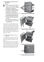
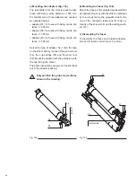
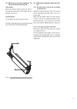
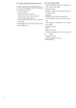
With the contactor racked out of the switchgear,
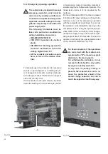
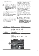
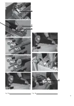
unscrew the four fixing screws of the shield and
relative DIN washers (fig. 17a) and position it
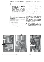
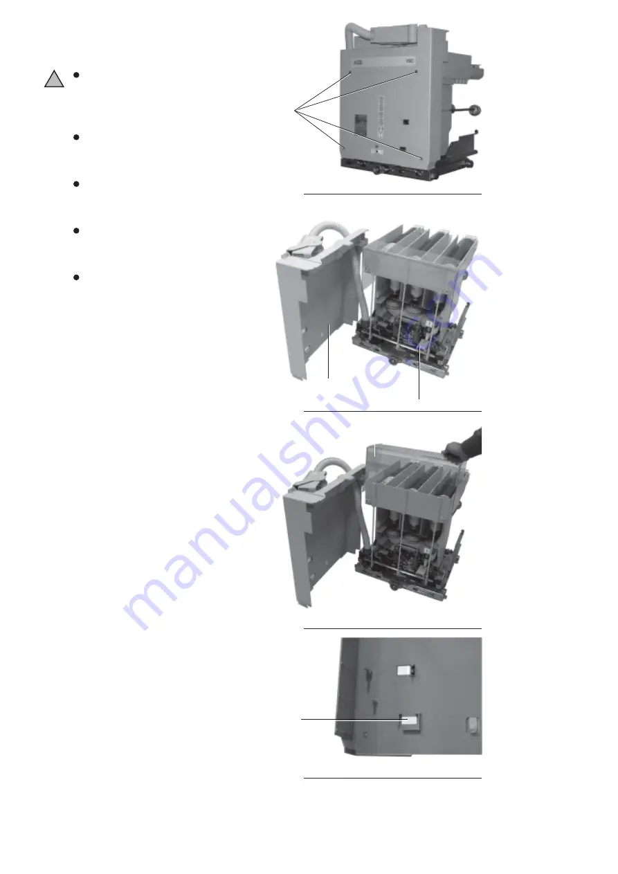
as in fig. 17b. For 12 kV contactors, remove pro-
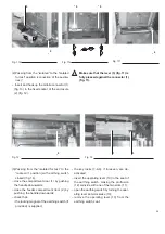
tection (2) and proceed to replace the fuses
according to the instructions given in par. 7.7.
!
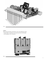
Fig. 17a
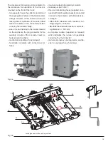
Fig. 17b
Fig. 17c
Fig. 17d
Summary of Contents for V-Contact VSC 12
Page 1: ...V Contact VSC Installation and service instructions 7 2 12 kV 400 A ...
Page 2: ...1 ...
Page 35: ...33 50 50 49 49 Fig 18c Fig 18b ...
Page 39: ...1 ...

