background image

1

Summary of Contents for V-Contact VSC 12

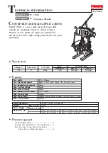
Page 1: ...V Contact VSC Installation and service instructions 7 2 12 kV 400 A ...

Page 2: ...1 ...

Page 3: ...o that installations according to the rules of good work ing practice and safety in the work place are constructed Strictly follow the information given in this instruction manual Check that the rated performance of the apparatus is not ex ceeded during service Check that the personnel operating the apparatus have this in struction manual to hand as well as the necessary information for correct in...

Page 4: ...General 12 5 2 Installation and operating conditions 12 5 3 Normal conditions 12 5 4 Special conditions 12 5 5 Overall dimensions 13 5 6 Assembly and making the connections 15 5 7 Description of the closing and opening operations 20 5 8 Manual emergency opening operation 22 6 Putting into service 23 6 1 General procedures 23 6 2 Racking the contactor in and out 24 6 3 Accessories and tools for the...

Page 5: ...sories and or spare parts For further information also see the 1VCP000165 technical catalogue of the contactor and the spare parts catalogue This manual and all the enclosed drawings must be considered an integral part of the apparatus They must be easily to hand at all times for revision and reference These instructions do not intend to cover all the details configurations or variants of the appa...

Page 6: ...thstand voltage at power frequency according to the IEC 60694 Standard is safe application of a voltage higher than the withstand voltage at power frequency or of a direct current test voltage specified in the IEC Standard cannot be used limitation of the above mentioned local phenomena on interrupters with open contacts de pends on keeping the specified distance between the contacts This conditio...

Page 7: ... procedures and the local regulations in force 4 is qualified and authorised to put this apparatus into service and to carry out maintenance and repair operations on it 5 is trained in correct use of protective equipment such as rubber gloves hard hats protective goggles face shields flameproof clothing etc according to the safety procedures and the local regulations in force 6 is trained in first...

Page 8: ...he actuator Bistable MAC drive for medium voltage contactors The drive is operated by means of an electronic feeder which with just three versions can cover all the power supply voltage values required by the major international Standards 1 1 MAC magnetic drive Based on the experience gained in the field of circuit breakers with magnetic drive ABB has implemented this technology in the field of co...

Page 9: ...3min CO A 4 107 6 104 15 000 8 000 15 000 8 000 Opening time with electrical latching ms 20 30 20 30 20 30 20 30 Closing time ms 30 50 30 50 30 50 30 50 Weight Kg 20 20 49 49 Overall dimensions mm H 371 391 635 635 mm W 350 350 531 531 mm D 215 215 657 657 Tropicalisation 721 2 1 1 3 Characteristics Without fuses The energy needed for operation is not sup plied directly by the auxiliary power supp...

Page 10: ...d current and breaking capacity in category AC11 and DC11 Un Cos ϕ T In Icu 220 V 0 7 2 5 A 25 A 24 V 15 ms 10 A 12 A 60 V 15 ms 6 A 8 A 110 V 15 ms 4 A 5 A 220 V 15 ms 1 A 2 A 1 5 Contactor auxiliary circuits 10 auxiliary contacts 5 normally open and 5 normally closed are available on the contactor for the customer s use with the following characteristics 1 6 Compliance with Standards V Contact c...

Page 11: ...g and the colour of the SHOCKWATCH indicator Fig 1 placed on it If the SHOCKWATCH impact indicator is WHITE it means that the packing has not re ceived any notable shocks during transport Open the packing remove the contactor as in dicated below and check the state of the ap paratus and its correspondence with the name plate data see fig 2 with what is specified in the accompanying shipping note a...

Page 12: ...x the contactor onto the truck or onto the transport plate pallet to prevent it moving or tilting over 3 1 Handling using a lifting or fork lift truck 5 Avoid excessive speed sudden starts and stops or sharp changes in direction during contactor handling 6 Only lift the contactor enough to avoid any obstacles on the floor 7 Take care to avoid any impacts with struc tures other apparatus or with pe...

Page 13: ...atic condi tions if it is left without protection rust and de terioration of the insulation can occur Insert special hygroscopic packets inside the packing with at least one standard packet per piece of apparatus Replace the packets ap proximately every 6 months Should the original packing no longer be avail able and immediate installation is not possible store in a covered well ventilated dry dus...

Page 14: ...eral Correct installation is of primary importance The manufacturer s instructions must be care fully studied and followed It is good practice to use gloves for handling the pieces during in stallation The areas involved by the passage of power conductors or conductors of the auxiliary circuits must be pro tected against access of any animals which might cause damage or disser vices The contactor ...

Page 15: ...istances between fixing holes refer to figure 4a In any case avoid stressing the supporting structure of the contactor if necessary arrange slots in the fixing area to facilitate correct positioning of the apparatus The assembly positions can be selected between the two shown in figure 4b Fig 4a ...

Page 16: ...ors The contactor keeps its performances in the installation positions indicated A floor mounted with moving contacts at the bottom B wall mounted with horizontal moving contacts and terminals at the bottom Fig 4b 5 5 2 VSC P withdrawable contactors Fig 5 ...

Page 17: ...ces of oxi dation clean with a very fine grain emery cloth taking care not to remove the surface layer if necessary restore the surface treatment consult ABB put the connections in contact with the contactor terminals taking care to avoid mechanical stresses produced for example by the conductor busbars on the terminals themselves Introduction Before carrying out any installation operations Test a...

Page 18: ...nary output n 1 Indication of Unit ready pole 1 KM1 4 Binary output n 1 Indication of Unit ready pole 2 KM1 5 Binary input n 1 Protection trip pole 2 KM1 6 Binary input n 1 Protection trip pole 1 KM1 7 Binary input n 2 Closing pole 1 KM1 8 Binary input n 2 Closing pole 2 KM1 9 Binary input n 3 Opening pole 1 KM1 10 Binary input n 3 Opening pole 2 KM1 11 Binary input n 3 Undervoltage pole 1 KM1 12 ...

Page 19: ... KM1 6 KM1 7 KM1 8 KM1 9 KM1 10 KM1 11 KM1 12 Fig 6 Checks After the above mentioned operations carry out the following checks check that the connections do not exert any force on the terminals check tightness of the connections Fig 7 ...

Page 20: ...p part of the protection there are strik ers 30a and 30b for actuating the enclo sure contacts to signal protection connected isolated The pin 34 for locking contactor racking in with the earthing switch closed on the enclo sure comes out on the right side of the truck 28 5 6 2 Withdrawable contactors and enclo sures The withdrawable contactors are used in the UniGear ZS1 type switchgear and in th...

Page 21: ...ircuits of the contactor must be hooked up to the stake mechanical signalling of open closed fuseholder complete with connections for fuses input and output tulip isolating contacts locks as per par 5 6 2 1 three current limiting fuses supplied on re quest with high breaking capacity connected in series to the contactor with dimensions ac cording to DIN 43625 Standard with maximum car tridge lengt...

Page 22: ...s of the shutters and in the closed and or open posi tion Electric lock on racking in and racking out with the door open microswitch on the door of the enclosure connected in series with the locking electromagnet on the contactor truck Key lock on earthing truck racking in with the lock activated all the operations with the contactor are possible but positioning the earthing truck in the isolated ...

Page 23: ...e Command Operated Power supply in an impulsive way of the closing input 30 ms minimum impulse time Power supply in an impulsive way of the opening input 30 ms minimum impulse time If the closing command persists at the same time the contactor opens since the opening command has priority In this situation the contactor remains in the open position due to the integrated anti pumping function until ...

Page 24: ...n In any case if auxiliary voltage is present take special care not to re move the protective shield of the stored energy capacitor and not to touch the capacitor itself in any way 5 8 Emergency opening operation The contactor is provided with manual emergency operation which must be carried out by suitably qualified per sonnel with in depth knowledge of the apparatus and with voltage to the ap pa...

Page 25: ... operations as well as those indicated in the table check that the voltage and current applied are within the specified rated values check tightness of the power connections of the fixed contactors and integrity of the iso lating contacts of the withdrawable contactors carefully clean the sheets and insulating parts with brushes and clean dry cloths Avoid us ing jets of compressed air check the ea...

Page 26: ...rest it on Fig 11a Fig 11b the handling truck 1 fig 11a following the instructions given in par 3 2 Handling the contactor with a crane open the compartment door move the truck close to the switchgear fig 11a insert the hooking bracket 4 fig 11b c and lock the wheels 3 fig 11a release the contactor from the truck by mov ing the two handles 5 fig 11d at the same time towards the median axis of the ...

Page 27: ...shing the handle downwards close the feeder compartment door 2 by pushing the handle downwards check that the locking magnet of the earthing switch if provided is supplied Fig 13 the key locks 7 8 9 if foreseen are de activated insert the operating lever 13 in the seat of the earthing switch making the protrusion 12 coincide with one of the two slots 11 open the earthing switch by turning the oper...

Page 28: ...est position with contactor open fig 14 Fig 14 Caption to the key locks of the earthing switch 7 lock with earthing switch open 8 lock with earthing switch closed 9 lock on contactor racking in through the inspection window 4 check that the contactor is open indicator in position O fully insert the racking in out lever of the truck 3 fig 15 in the corresponding coupling 5 and turn it anti clockwis...

Page 29: ... Operating lever of the earthing switches 2 Contactor racking in out lever 3 Tool for manual emergency opening operation Fig 15 move the two handles 5 fig 11d at the same time towards the median axis of the contactor and simultaneously pull the con tactor progressively towards the outside on the truck by means of the handles let go of the handles and continue extraction until the contactor locks w...

Page 30: ...chapter the regulations and specifications in the country of in stallation It is good practice to keep a maintenance card and a service book where all the operations carried out can be noted down in detail together with the date description of the anomaly and the references of data needed to identify the apparatus etc see chapter 2 Experience gained in use of the apparatus will allow the optimal t...

Page 31: ...any cabling straps are loose or broken and check connection tightness Examine all the wire or cable connections to make sure that none of them are loose and that there is no over heating The isolating contacts must be free of any deformation or erosion Lubricate the contact elements with 5RX Moly type grease Item to be inspected 1 Insulating parts 2 Structure 3 Interrupter 4 Interrupter contacts 5...

Page 32: ...pparatus and carry out the repairs or replacements neces sary before putting the apparatus back into service Make sure that all the spare parts when re quired are suitable for the application In case of any doubts please contact ABB Have a complete check of the contac tor carried out by ABB personnel af ter 1 000 000 operations or 10 years of operation Contact ABB Service Assistance Vacuum interru...

Page 33: ...with the dimensions and average type of striker according to DIN 43625 1983 and BS 2692 1975 Standards and with electrical charac teristics according to IEC 282 1 1974 Stand ards The fuseholder is always fitted with an au tomatic opening device for a fuse blowing This device prevents contactor closing when even a single fuse is missing 7 6 2 Preliminary operations for fuse re placement The contact...

Page 34: ... adapter packing b Dismantling the fuses fig 18b Open the locking rings 49 fig 18b moving them in the direction shown by the arrows us ing the tool 50 and remove the fuse using the special tool 50 c Mounting the fuses fig 18c Open the locking rings 49 moving them in the direction shown by the arrows using the tool 50 fig 18b fully insert the fuses with the con tacts fitted with striker on the oppo...

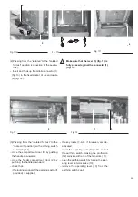
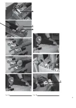
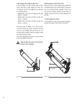
Page 35: ...33 50 50 49 49 Fig 18c Fig 18b ...

Page 36: ...2 fig 19b is preset to take fuses with fixing centre distance of 553 mm For smaller sizes three adapters are needed as indicated below adapter 51 for fuses with fixing centre dis tance l 235 mm adapter 52 for fuses with fixing centre dis tance l 305 mm adapter 53 for fuses with fixing centre dis tance l 454 mm Select the type of adapter fix it onto the fuse on the striker side by means of the grub...

Page 37: ... ice 7 9 1 Mounting the shield and insulating guard fig 14 Reposition the protection 1 fig 17b repeat ing the operations indicated in par 7 6 2 in re verse order Remount the shield Check that the impulse counter 14 fig 17c inserts itself into the spe cial seat 69 fig 17d and fix the shield with the screws 70 and DIN washers 71 fig 17a 7 9 2 Checking apparatus functions Rack the contactor into the ...

Page 38: ...vailability and to order spare parts please contact ABB Service 8 1 List of spare parts Vacuum interrupter assembly replacement to be carried out by ABB Electronic feeder Auxiliary contacts 5 normally open and or 5 normally closed Capacitor Interfacing shaft only fixed contactors 12 kV insulation shields only fixed contac tors Drive assembly replacement to be carried out by ABB Operation counter F...

Page 39: ...1 ...

Page 40: ...nnung GmbH Oberhausener Strasse 33 Petzower Strasse 8 D 40472 Ratingen D 14542 Glindow Phone 49 0 2102 12 1230 Fax 49 0 2102 12 1916 E mail calor info de abb com Internet http www abb de calor The data and illustrations are not binding We reserve the right to make changes in the course of technical development of the product 1VCD600192 Rev B en Instruction Manual 2005 12 V Contact VSC VSC P ...

Reviews: