10 CI/EDP300-EN Rev. A |
D500
Change from one to two columns
3
Mounting
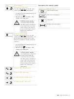
CAUTION – Minor injuries
Incorrect parameter valves can cause the valve to
move unexpectedly. This can lead to process
failures and result in injuries.
Before recommissioning a positioner that was
previously in use at another location, always reset
the device to its factory settings. Never start Auto
Adjust before restoring the factory settings.
3.1
Operating conditions at installation site
IMPORTANT (NOTE)
Before installation, check whether the positioner
meets the control and safety requirements for the
installation location (actuator or valve).
See the "Specifications” section on the data
sheet.
3.2
Mechanical mounting
3.2.1
General information
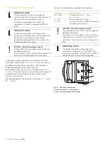
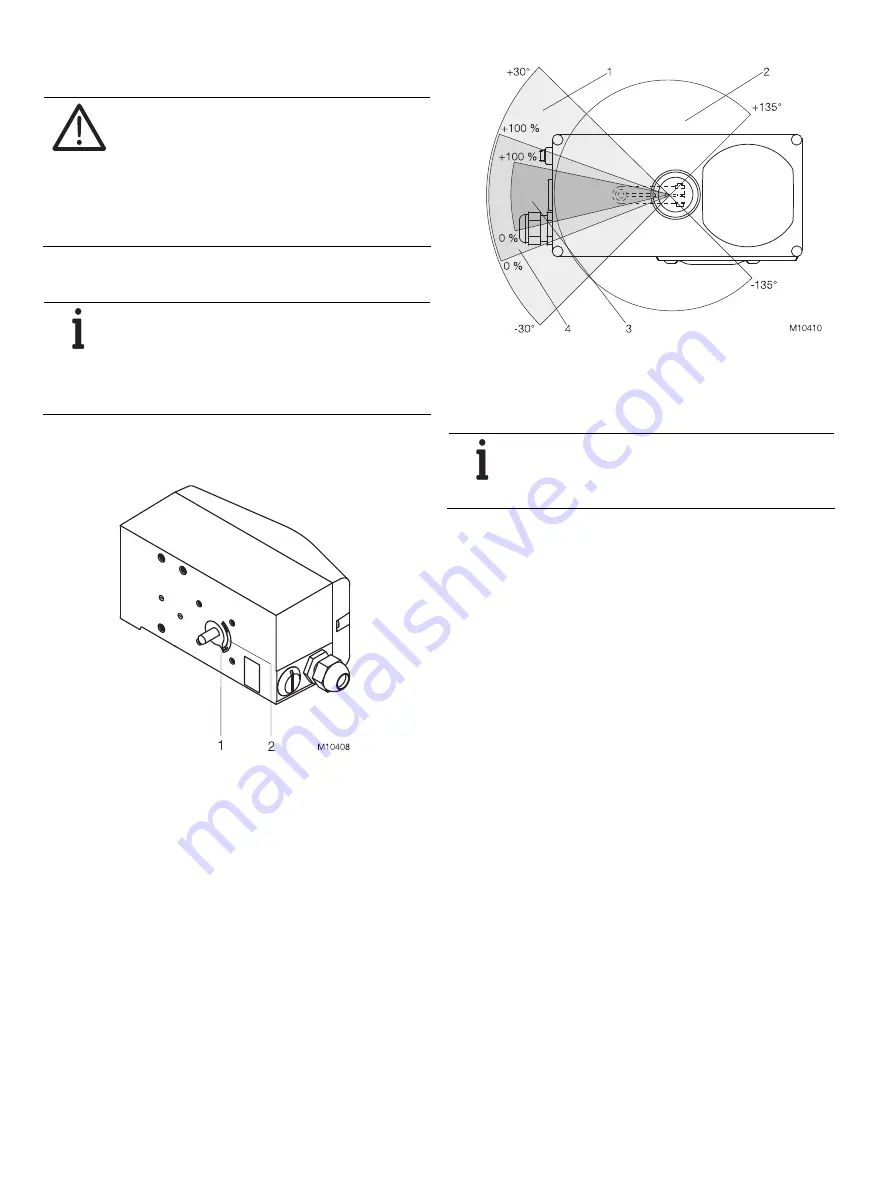
Fig. 2:
Working range
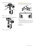
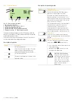
The arrow (1) on the positioner feedback shaft (position
feedback point) must move between the arrow marks (2).
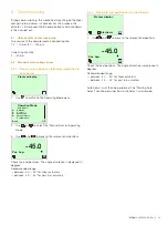
Fig. 3:
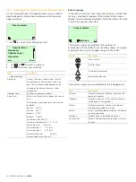
Sensor and operating ranges of the positioner
1 Sensor range for linear actuators |
2 Sensor range for part-turn actuators |
3 Working range for linear actuators |
4 Working range for part-turn actuators
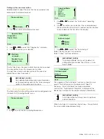
IMPORTANT (NOTE)
During installation make sure that the actuator
travel or rotation angle for position feedback is
implemented correctly.
The maximum rotation angle for position feedback is 60° when
installed on linear actuators and 270° on part-turn actuators.
The minimum rotation angle is always 25°.


